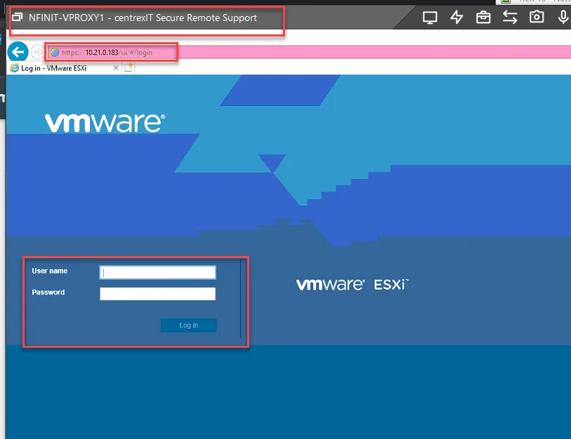
Configuring Boot From SAN and Upgrading to Vmware 7.0
Section titled “Configuring Boot From SAN and Upgrading to Vmware 7.0”Note: this only applies to our private cloud running HPE Synergy.
Evacuate VMs on host, Maintenance Mode, Shut Down
Section titled “Evacuate VMs on host, Maintenance Mode, Shut Down”Vmotion all VMs on the host you want to upgrade to other hosts. Once there are no more VMs on the host, set the host to maintenance mode, then shutdown host.
Update the Synergy 6820C 25/50Gb CNA firmware by Installing CP049786.exe on Host
Section titled “Update the Synergy 6820C 25/50Gb CNA firmware by Installing CP049786.exe on Host”Log into the Synergy OneView. Go to Servers, Server Hardware. Select the Server of the Server you are updating. Click on the iLO Address to log into the iLO.
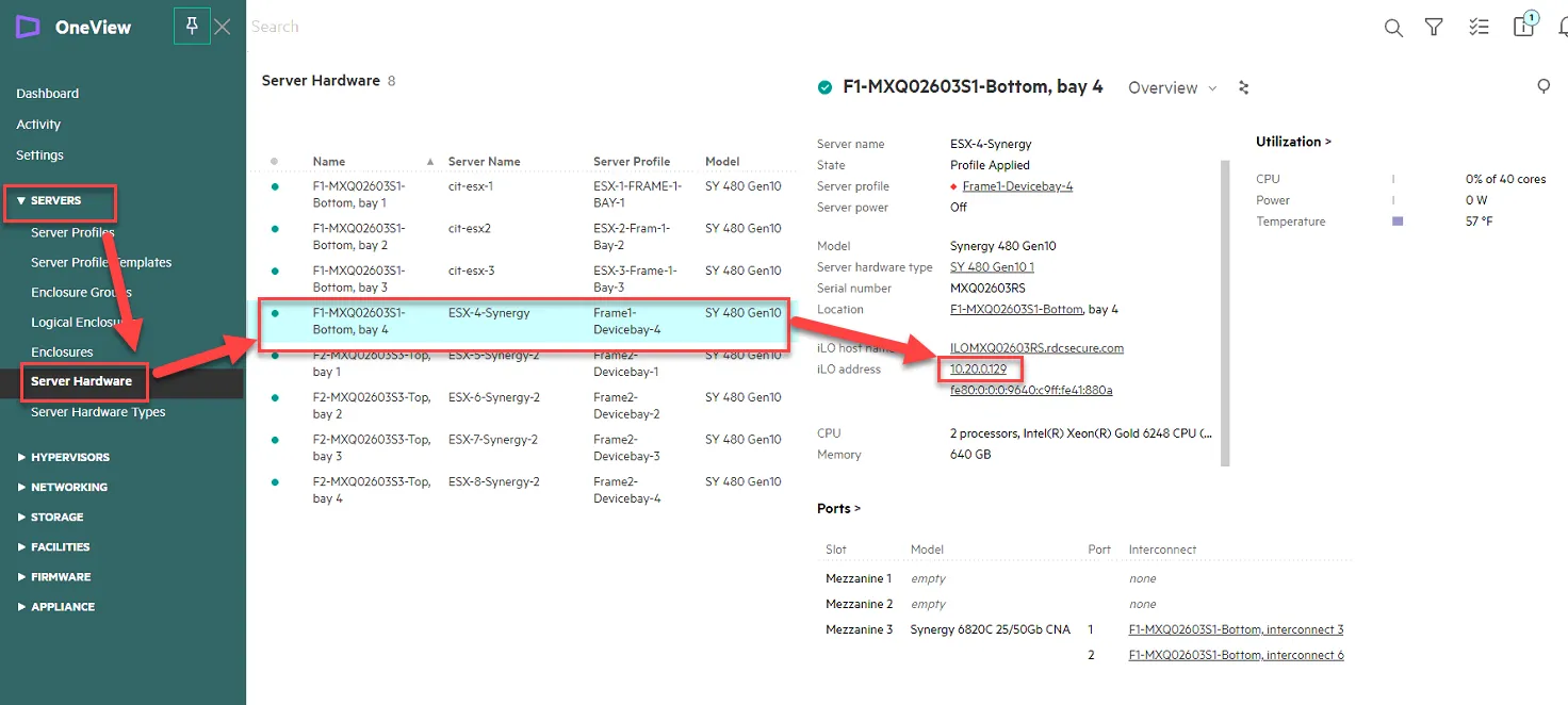
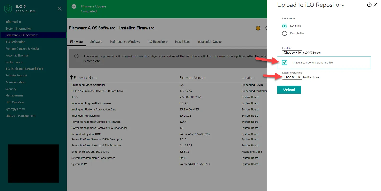
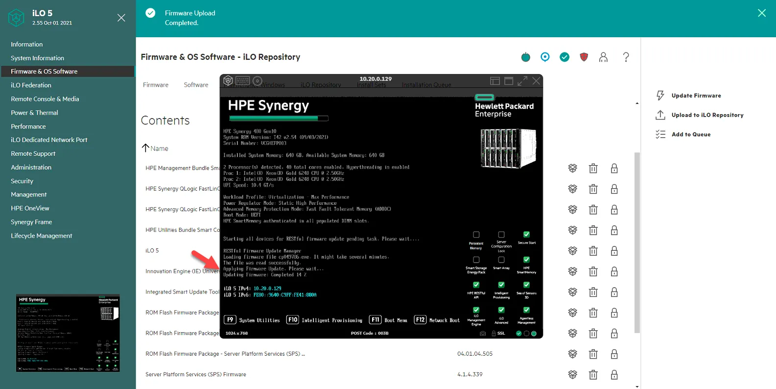
Once in the iLO, go to Firmware & OS Software, and Click Upload to iLO Repository.
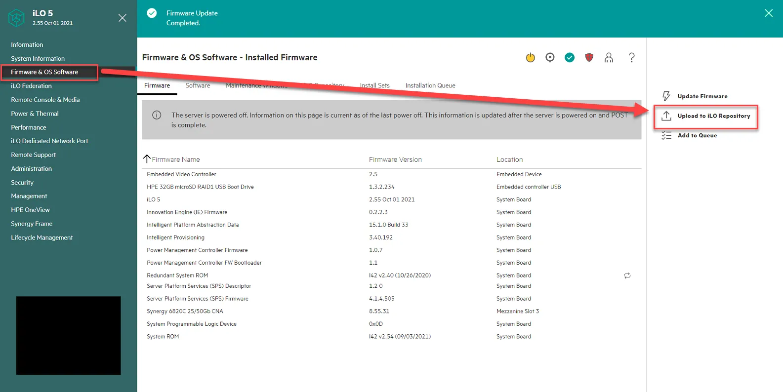
Select Local File, then click Choose File.
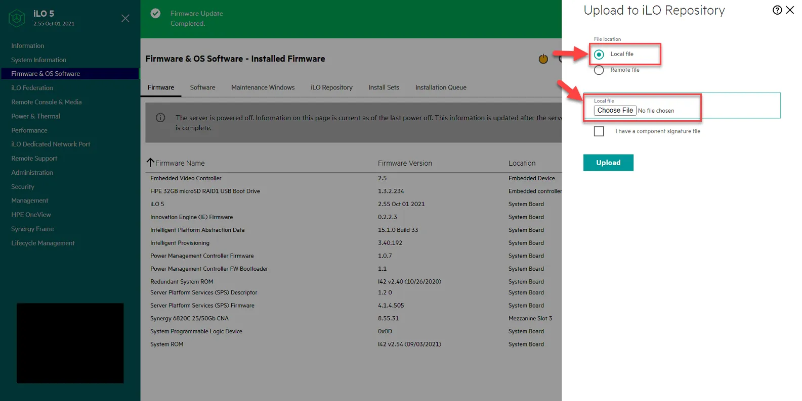
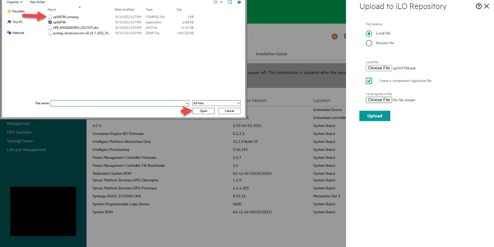
Select the file. Click Open. Note: you should have this already downloaded. If not, get file from Jomer or Andy.
Click box for I have a component signature file and click Choose File.
Select the compsig file, and click Open.
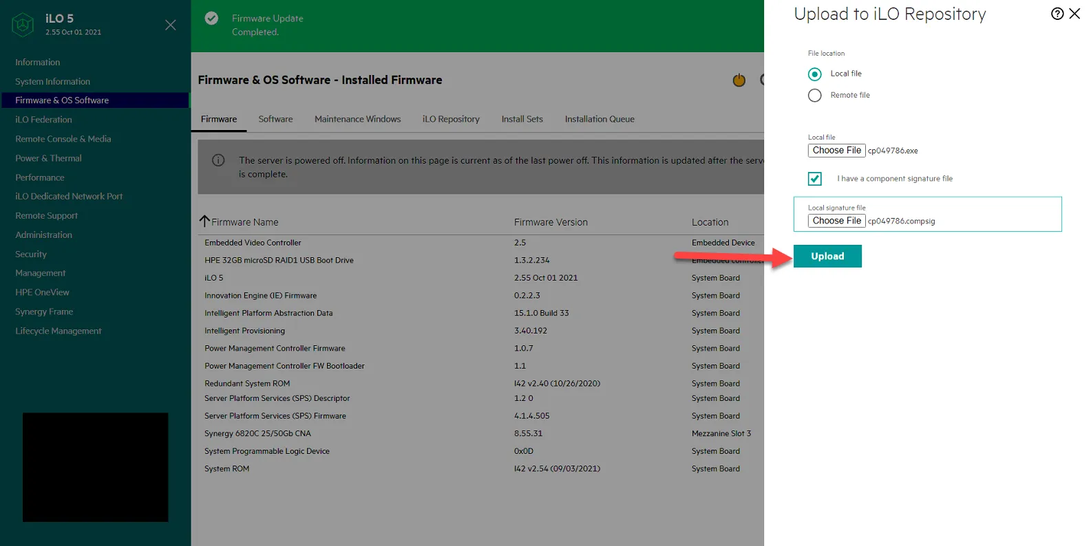
Click Upload. Then Click ok to Continue.
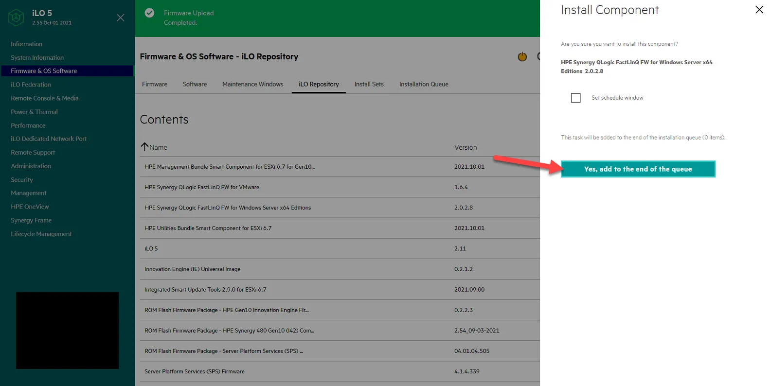
Once uploaded, click on iLO Repository. You should see HPE Synergy QLogic FastLinQ FW for Windows Server x64 Editions version 2.0.2.8. Click on the box to install it.
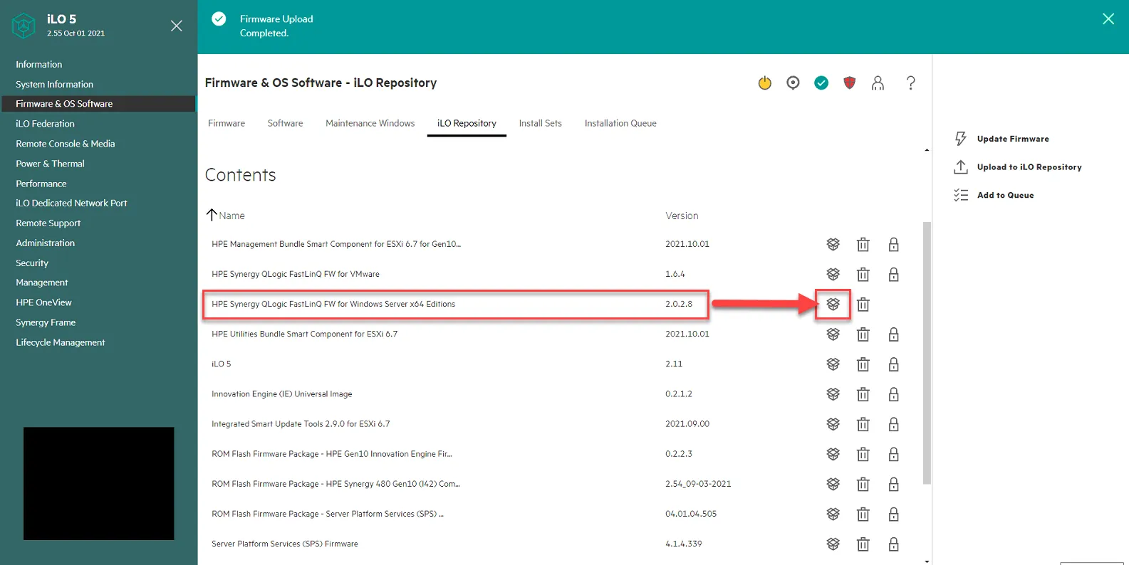
Click Yes, add to the end of the queue.
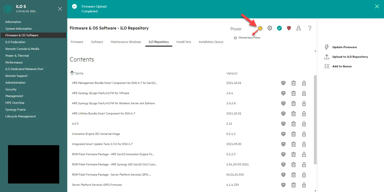
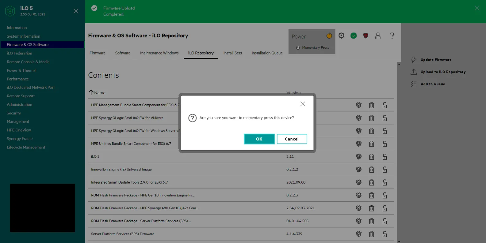
Power on server by clicking on the yellow power button, then selecting Momentary Press.
Click Ok
Click on the black console box and select HTML 5 to launch the console and watch it boot up.
As its booting you will see the driver being installed.
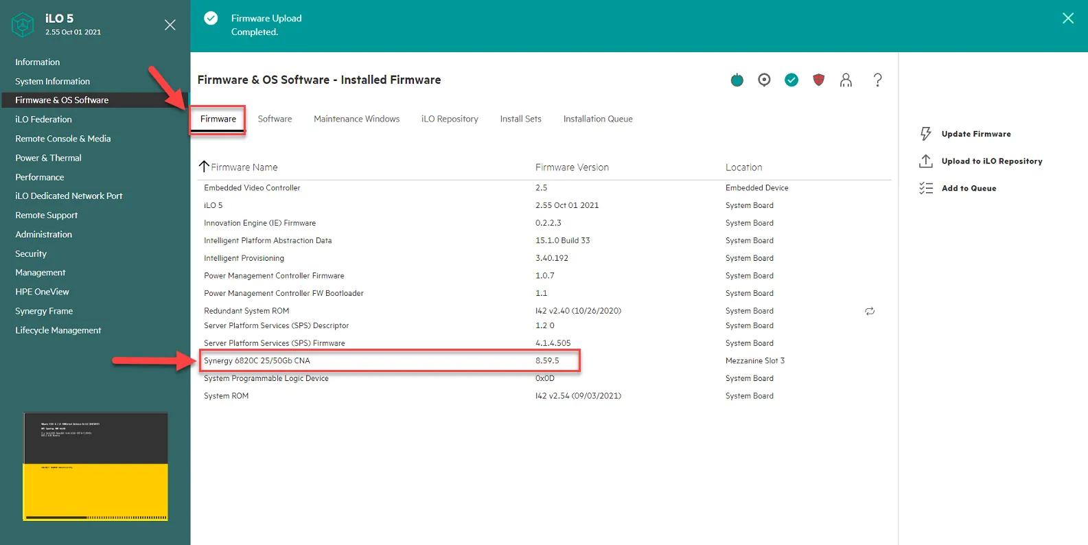
Once firmware is installed and server is booted, Click Firmware tab and confirm firmware version is 8.59.5.
Shutdown host once it is fully booted.
Create Dedicated BOOT LUN for the Host in CIT-Alletra-1
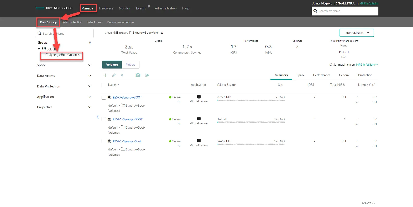
Section titled “Create Dedicated BOOT LUN for the Host in CIT-Alletra-1”Log into CIT-ALLETRA-1. Go to Manage, Data Storage, then Click Synergy-Boot-Volumes.
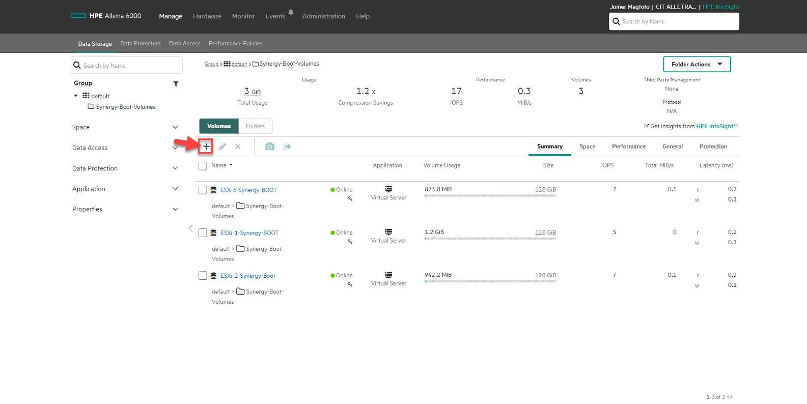
Click on + sign to create a new volume.
Set Name to ESXi-X-Synergy-Boot, where X is the number of the host. In this example, we are using ESXi-4-Synergy-Boot as the name.
Set Location to “default/Synergy-Boot-Volumes
Set Performance Policy to VMware ESX 5
Set size to 128GB
Set Data protection to Not Protected.
Set Access to ESXHost-x.x.x.x where x.x.x.x is the IP of the host. In this example we are selecting ESXHost-10.10.101.183.
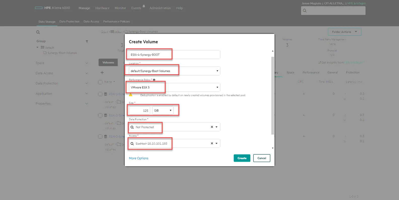
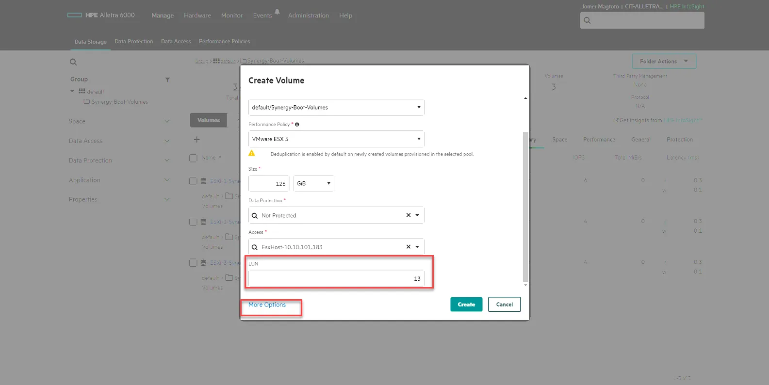
Scroll Down, Set LUN to the next unique number. Hint: check the previous host’s BOOT LUN number and use the next number above that. In this example, we are using LUN13.
Then click More Options.
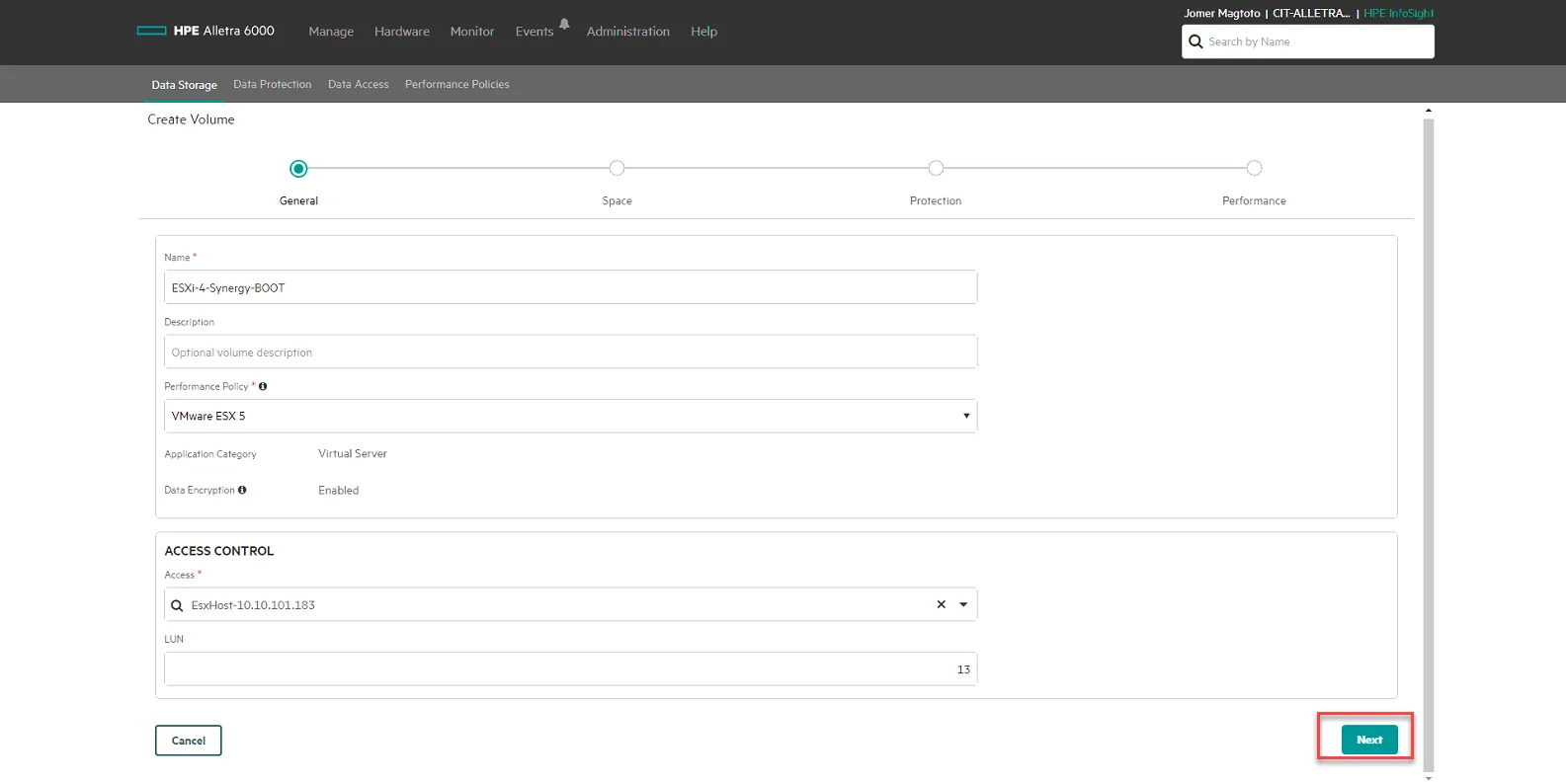
Click Next
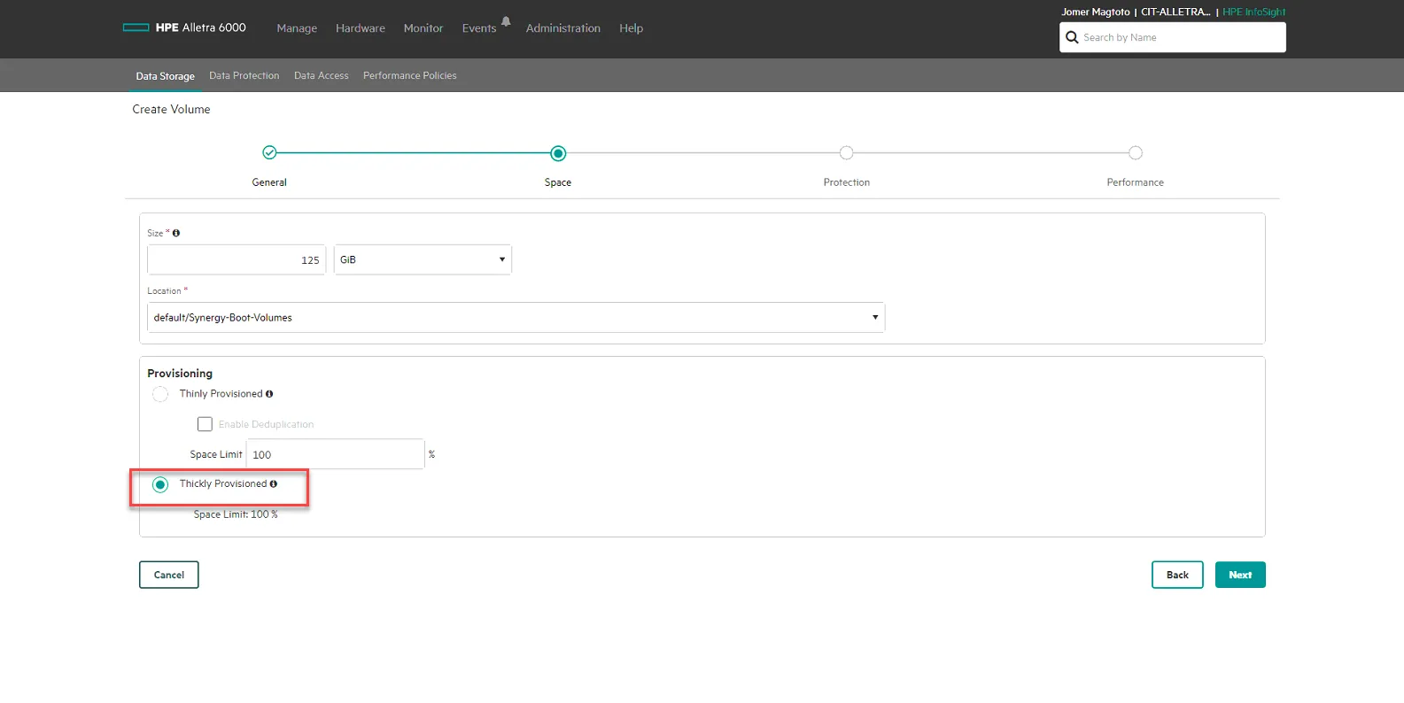
Uncheck Enable Deduplication, the select Thickly Provisioned. Click Next.
No Volume Collection, click Next.
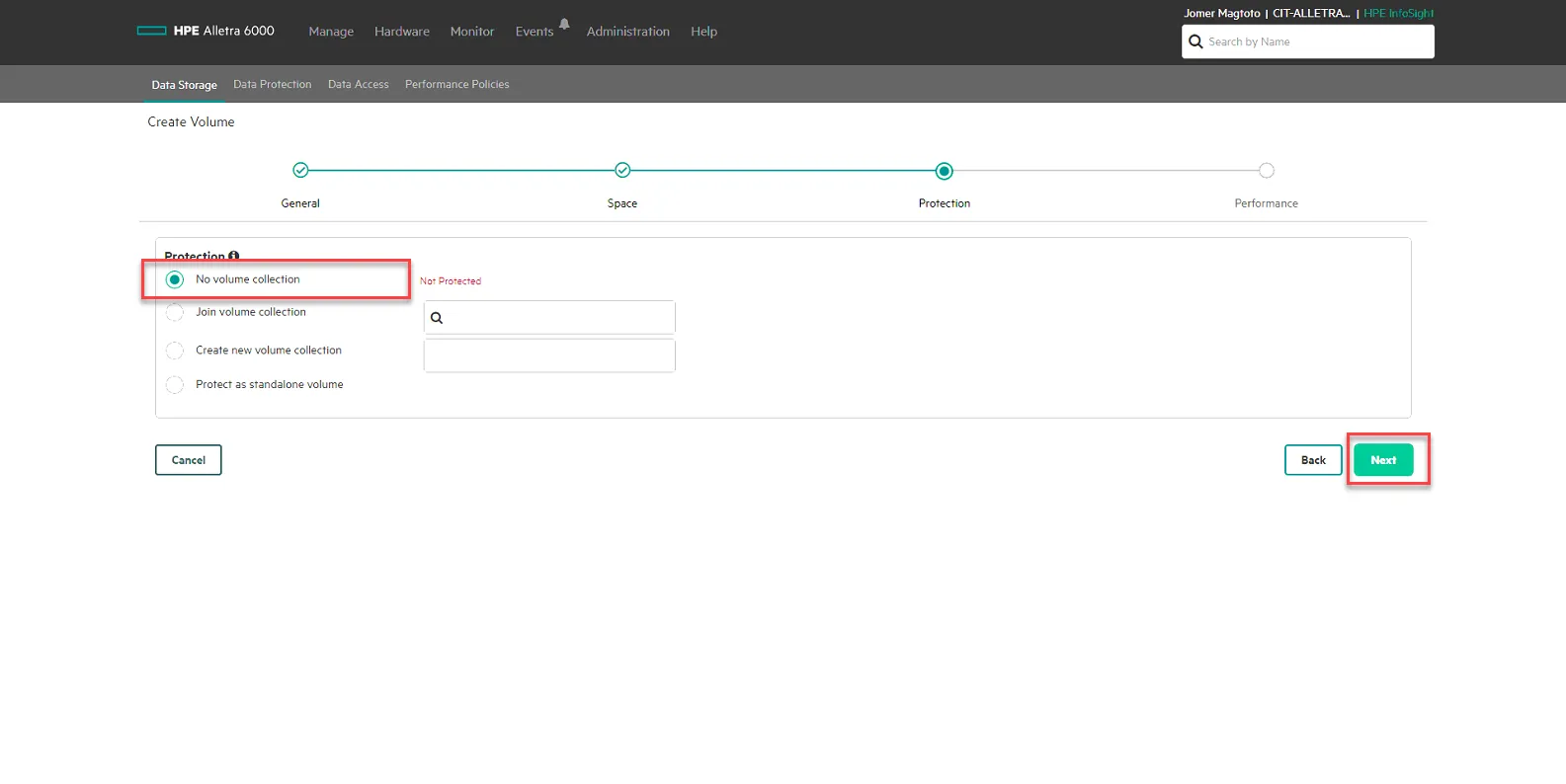
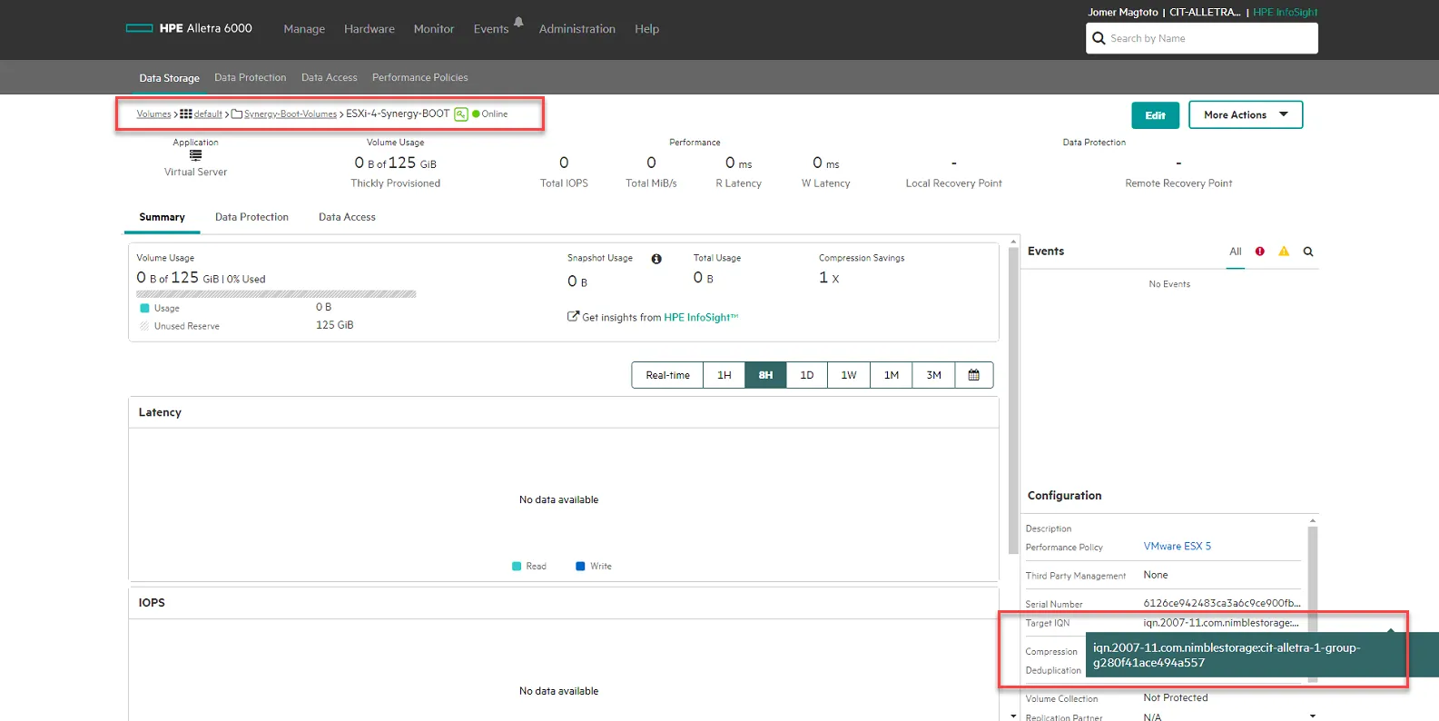
Then Click Create. Once it is created, click on your new BOOT LUN, and copy the Target IQN under Configuration. You will need this in the next steps when updating the ISCSI-A and ISCSI-B Initiator info in the next steps.
Remove Server Template and Create New Server Template
Section titled “Remove Server Template and Create New Server Template”Back in Synergy OneView, go to Servers, Server Profiles. Select the Server you are updating, Select Actions, then select Edit.
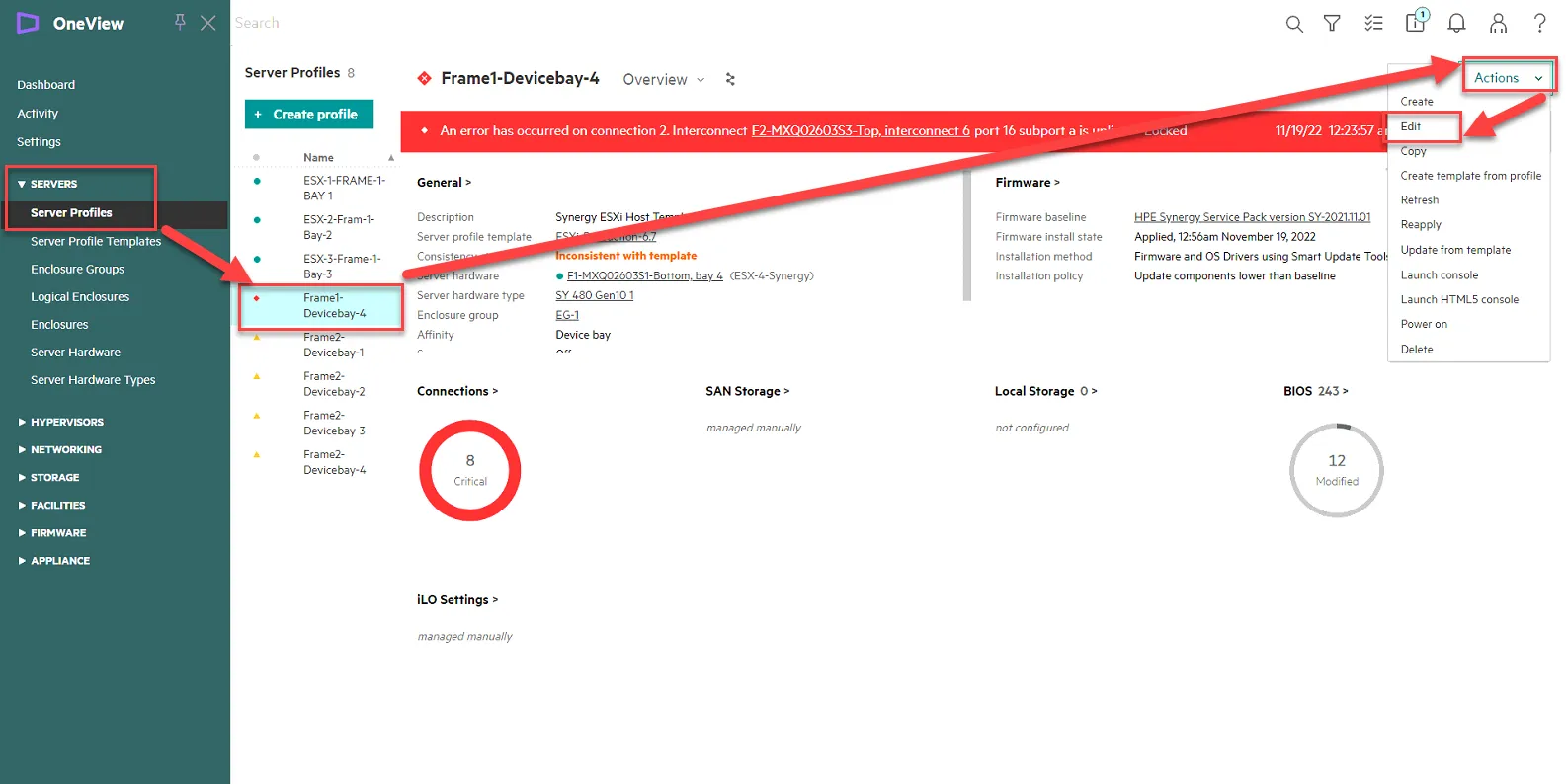
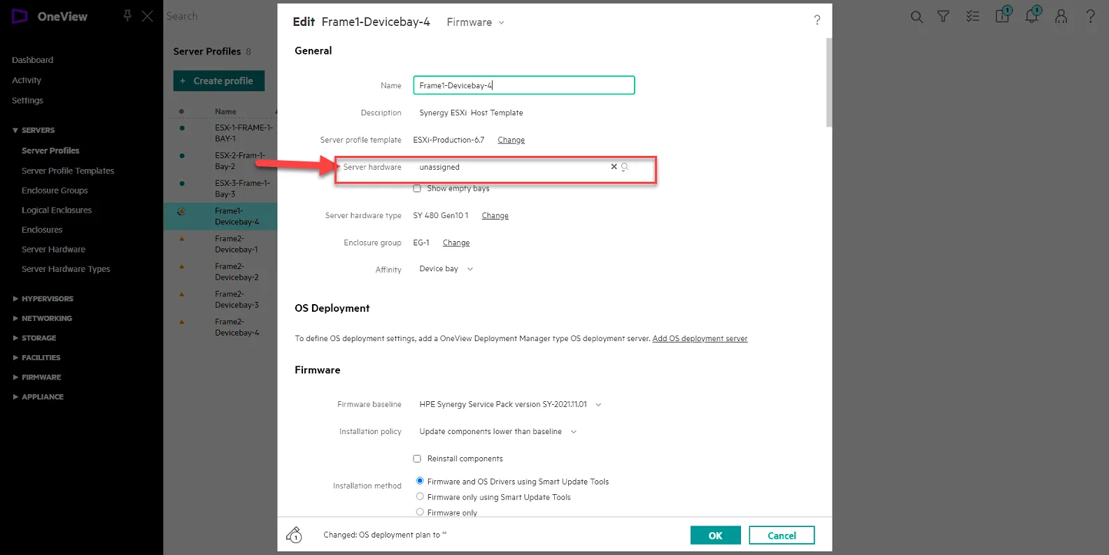
Set Server Hardware to unassigned, and click Ok to confirm.
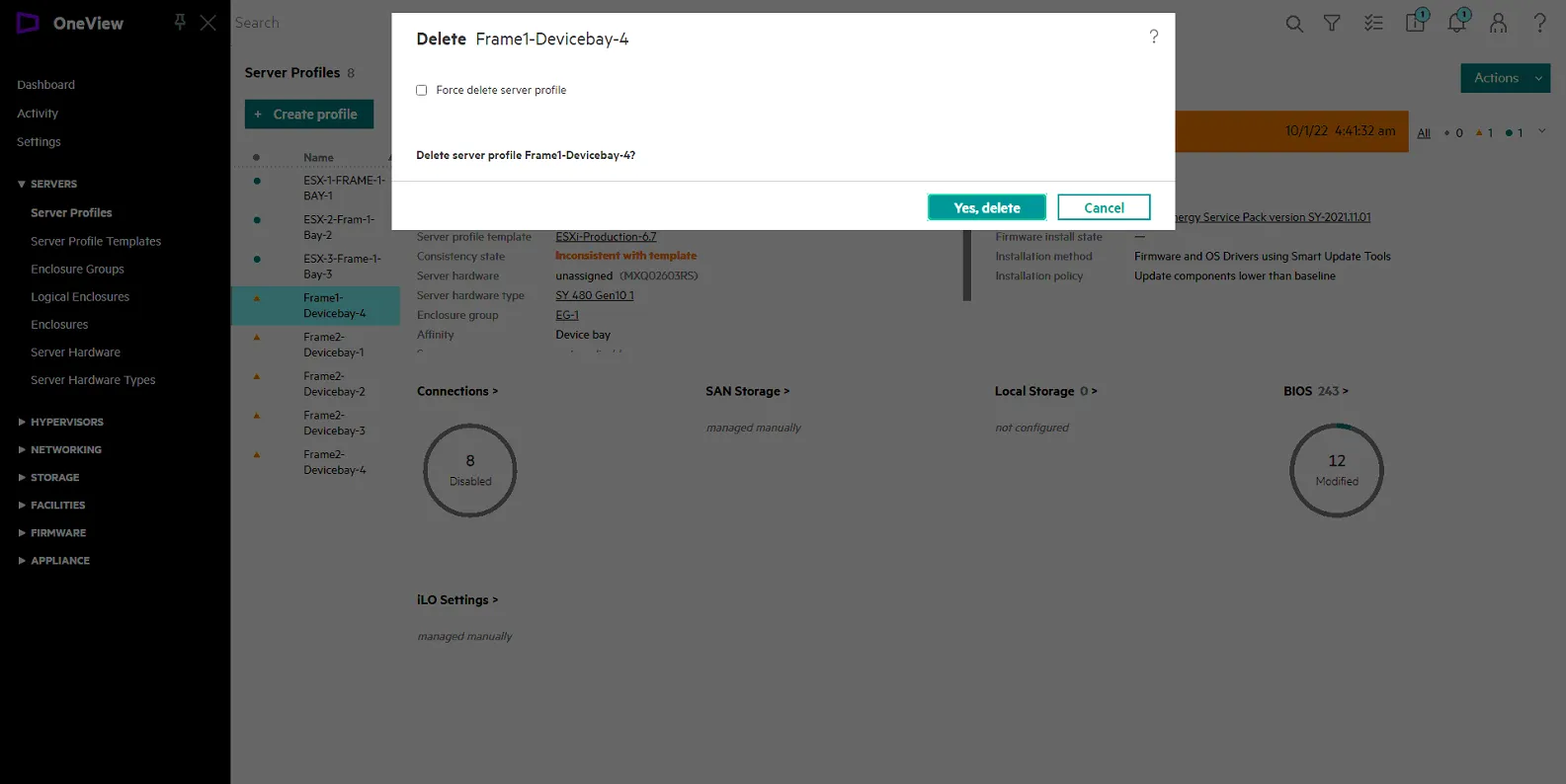
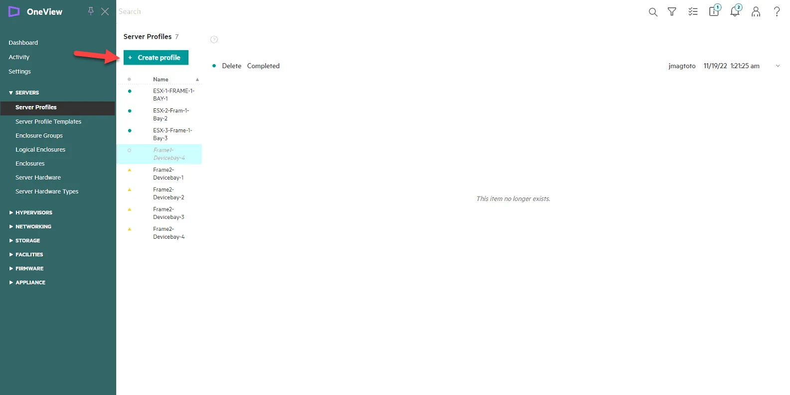
Click Action, then Click Delete to delete the server profile. ENSURE YOU ARE DELETING THE CORRECT ONE!
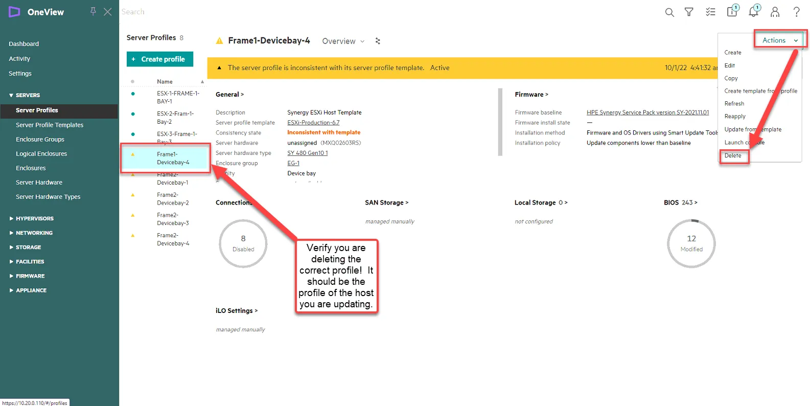
Click Yes, Delete.
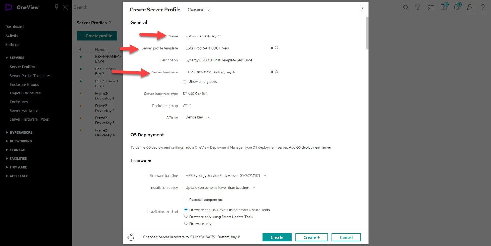
Create the new server profile. Click Create Profile.
Set name: ESX-X-Frame-Y-Bay-Z
Where X = Host Number
Where Y = Frame Number (1 or 2)
Where Z = Bay Number.
For example, this server we are upgrading is ESX-4-Frame1-Bay-4. Basing it off the old name, but adding ESX host number in the front.
Then set Server Profile Templarte to ESXi-Prod-SAN-BOOT-New
Then set Server Hardware to the available server hardware in the list.
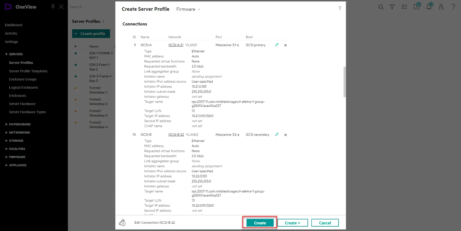
Scroll down to connections then set the Initiator IP and Target LUN information for ISCSI-A and ISCSI-B. Click the pencil to edit.
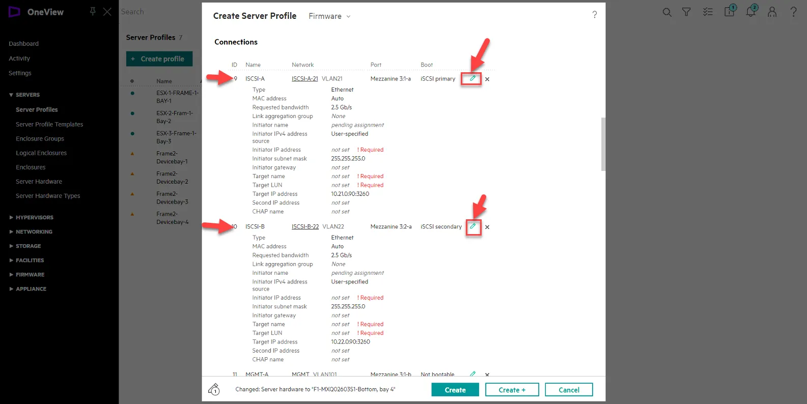
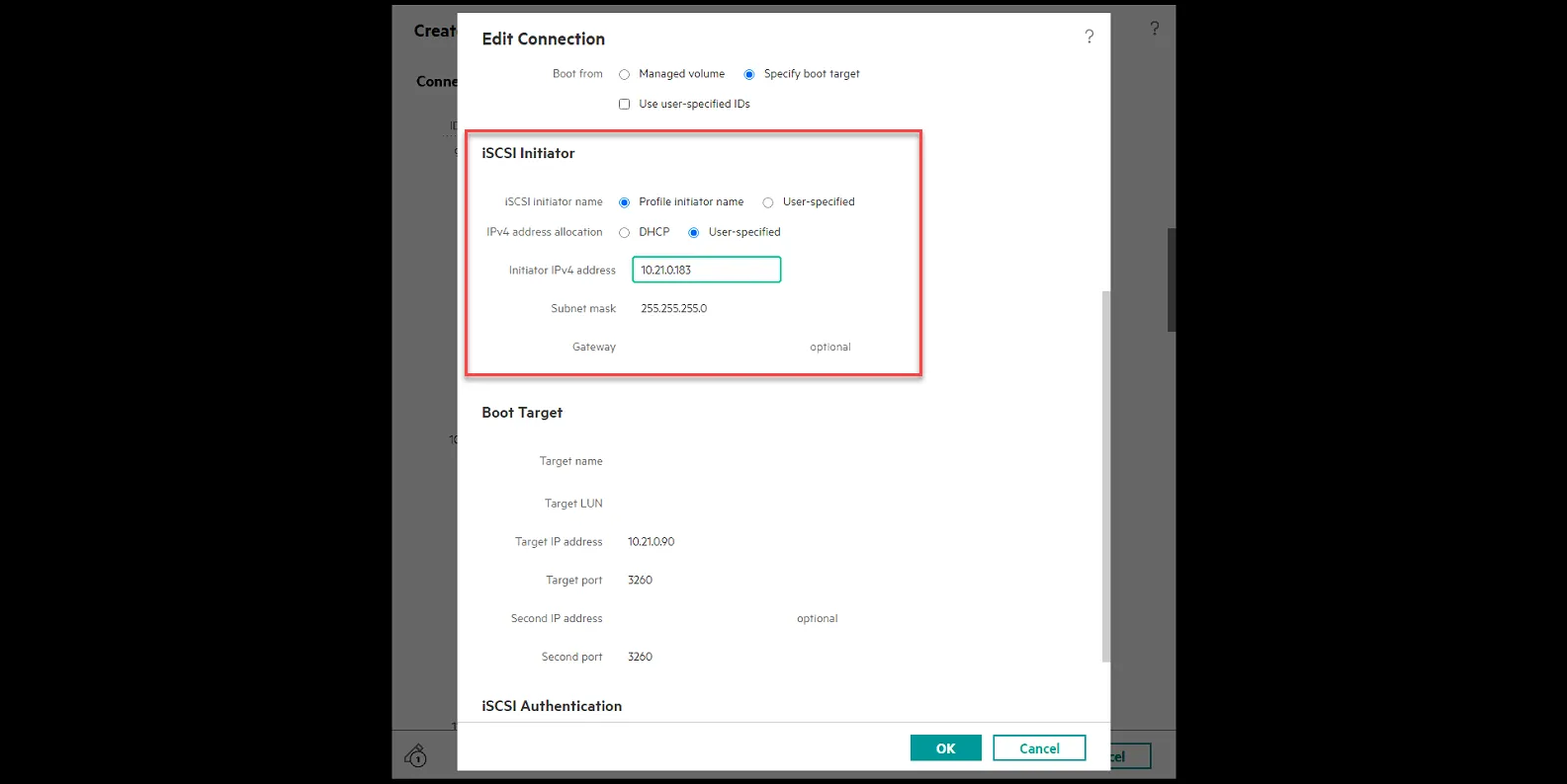
Edit ISCSI-A
ISCSI Initiator
initiator IPv4 Address - 10.21.0.183 (ISCS1-A is 10.21.0.x, and set the last octet to match the IP of the host)
Subnet Mask - 255.255.255.0
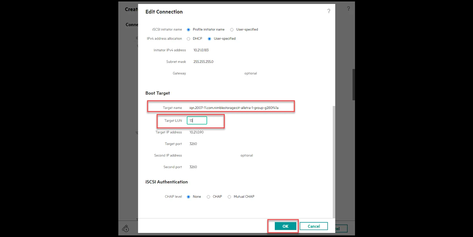
Boot Target
Target Name: type in the target IQN you copied in the previous steps when creating the LUN.
Target LUN: type in the unique LUN number you set your boot LUN to in the previous step when creating the LUN.
Click Ok.
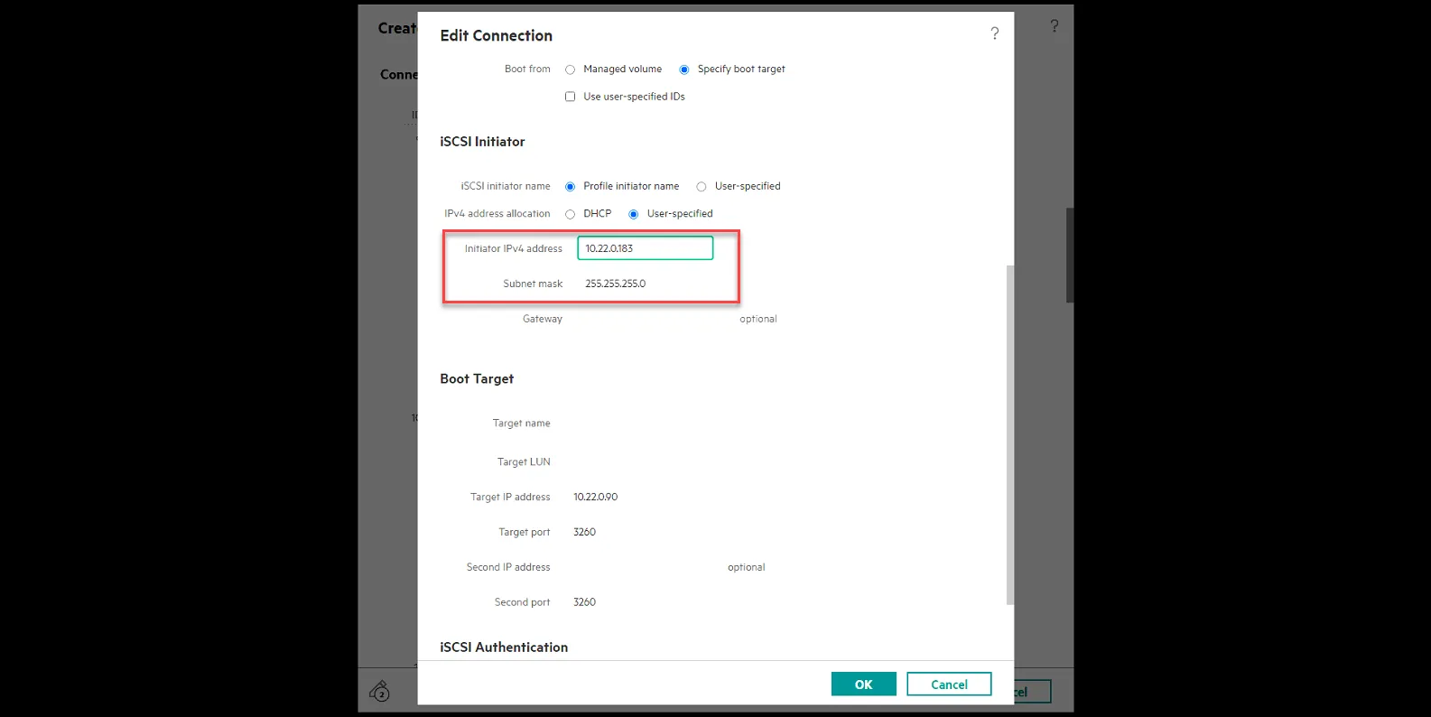
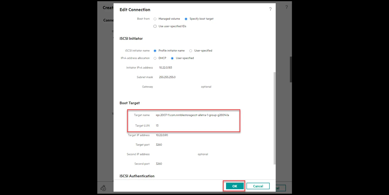
Edit ISCSI-B
ISCSI Initiator
initiator IPv4 Address - 10.22.0.183 (ISCS1-B is 10.22.0.x, and set the last octet to match the IP of the host)
Subnet Mask - 255.255.255.0
Boot Target
Target Name: type in the target IQN you copied in the previous steps when creating the LUN.
Target LUN: type in the unique LUN number you set your boot LUN to in the previous step when creating the LUN.
Click Ok.
Click Create
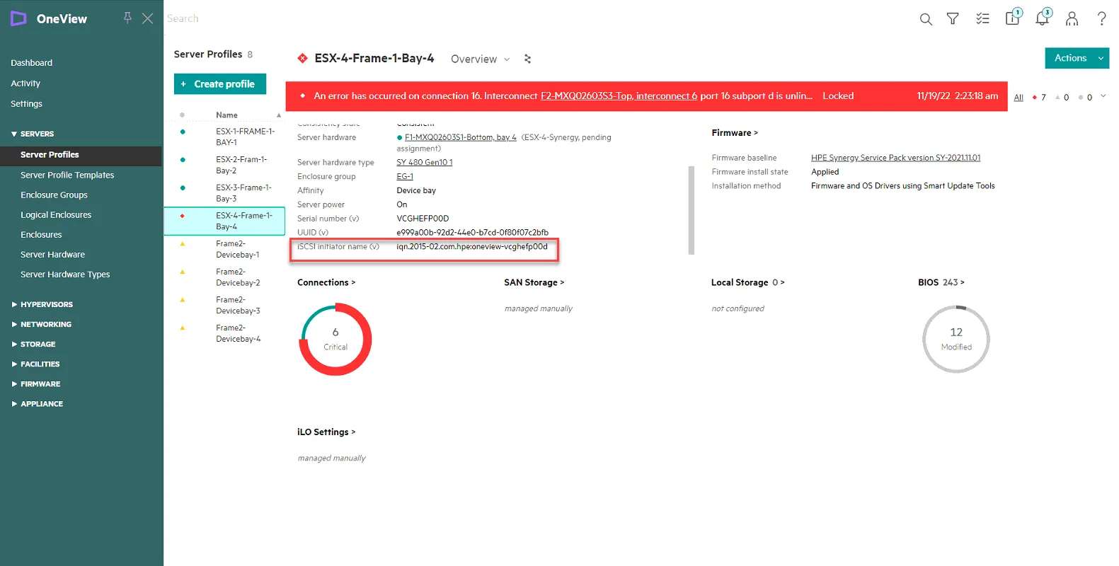
Once the profile is created, select the profile, and copy the iSCSI initiator name (v) entry. You will need to add this in the Alletra and Nimble 2.
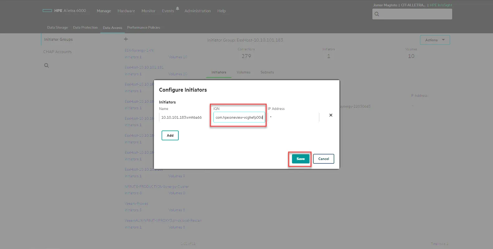
Update CIT-ALLETRA-1 and CIT-NIMBLE-2 Initiator Info for Host Access.
Section titled “Update CIT-ALLETRA-1 and CIT-NIMBLE-2 Initiator Info for Host Access.”Log into CIT-ALLETRA-1, Select Manage, then select Data Access. From there, select the host in question, then select the Pencil icon to edit it.
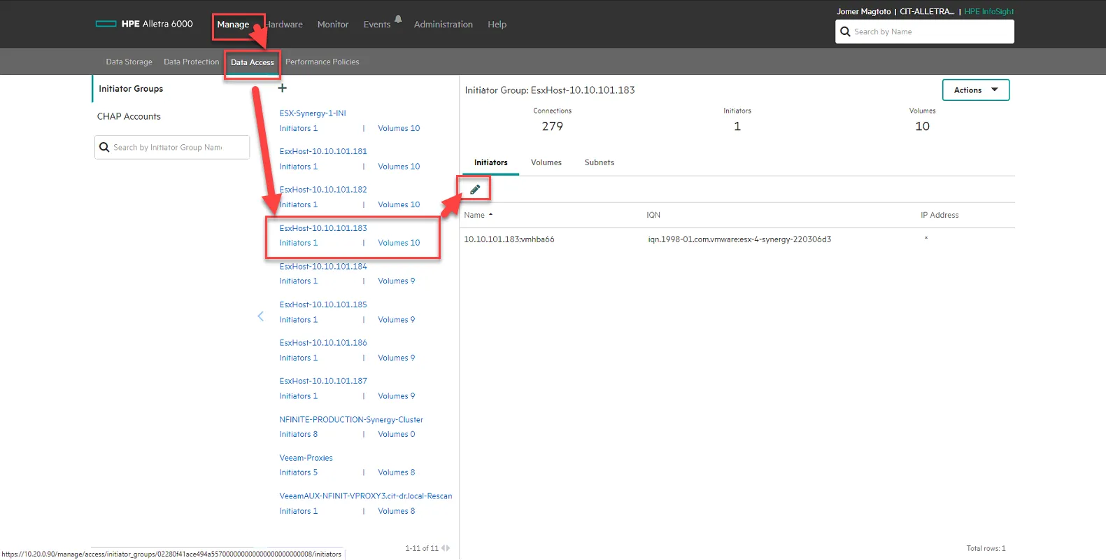
Update the IQN to the iSCSI initiator name (v) you obtained in the previous step. Click Save.
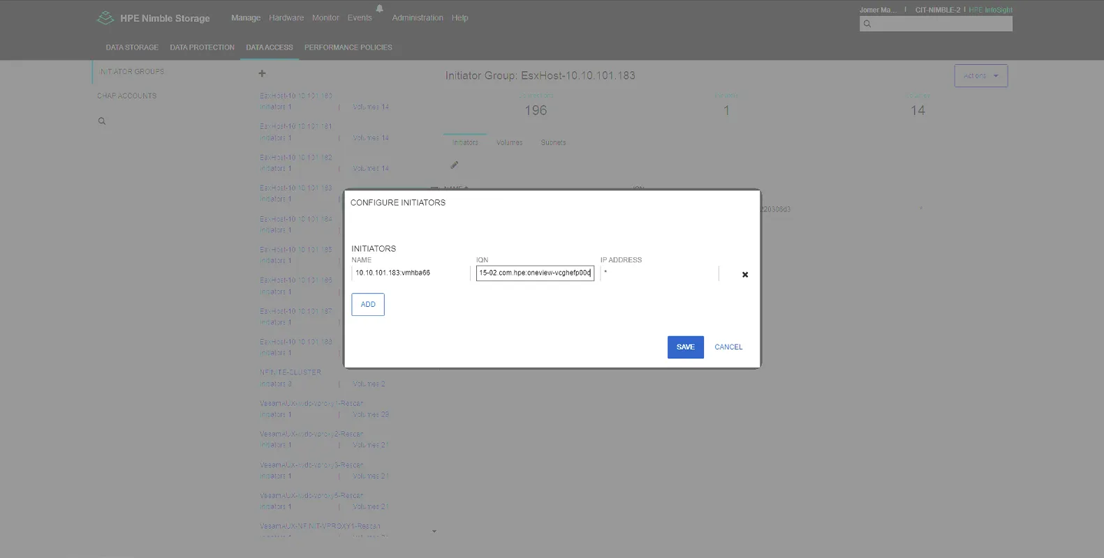
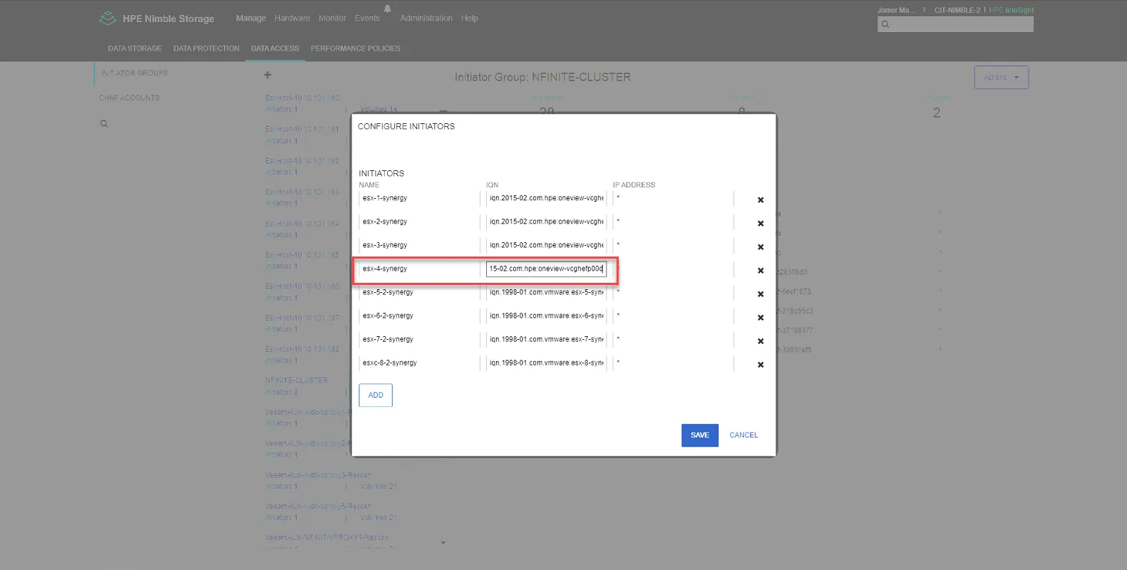
Log into CIT-NIMBLE-2, go to Manage, select Data Access, then select the ESXHost in question, then select the pencil to edit.
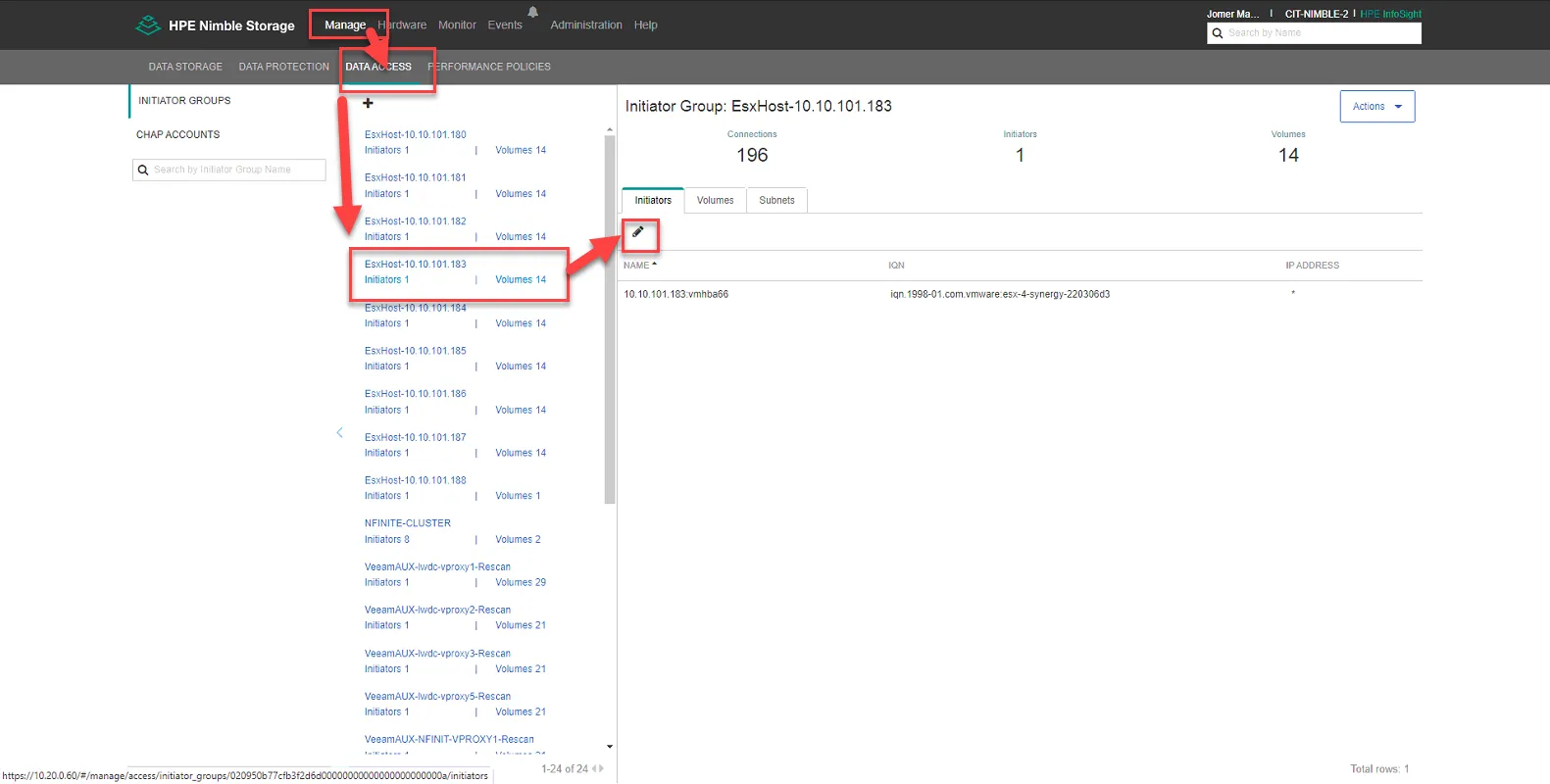
Update the IQN to the iSCSI initiator name (v) you obtained in the previous step. Click Save.
Select NFINITE-CLUSTER, then click the pencil to edit.
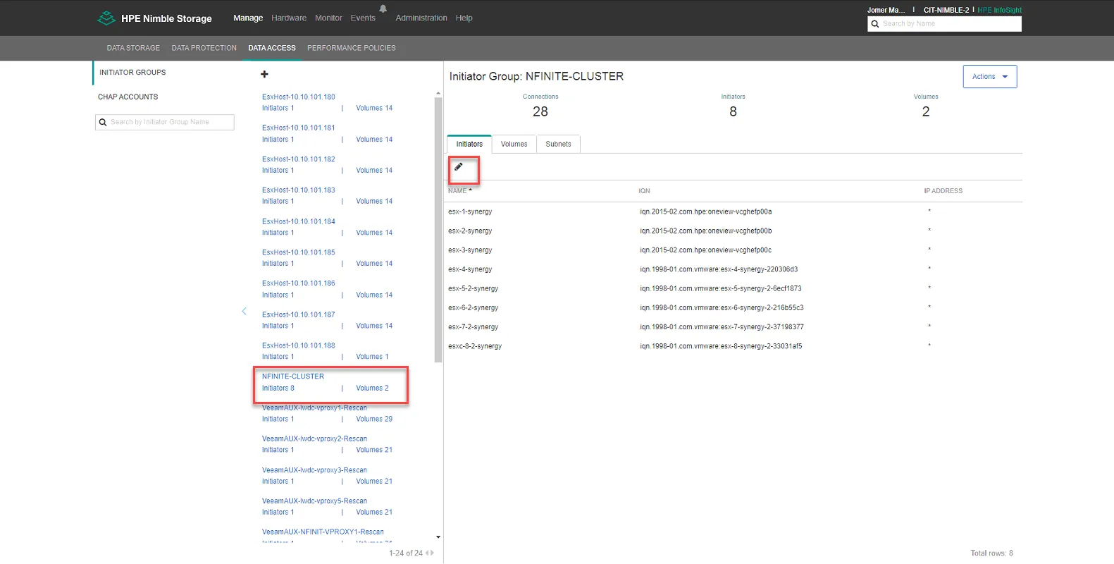
Update the IQN to the iSCSI initiator name (v) you obtained in the previous step for the correct hostname in question. Click Save.
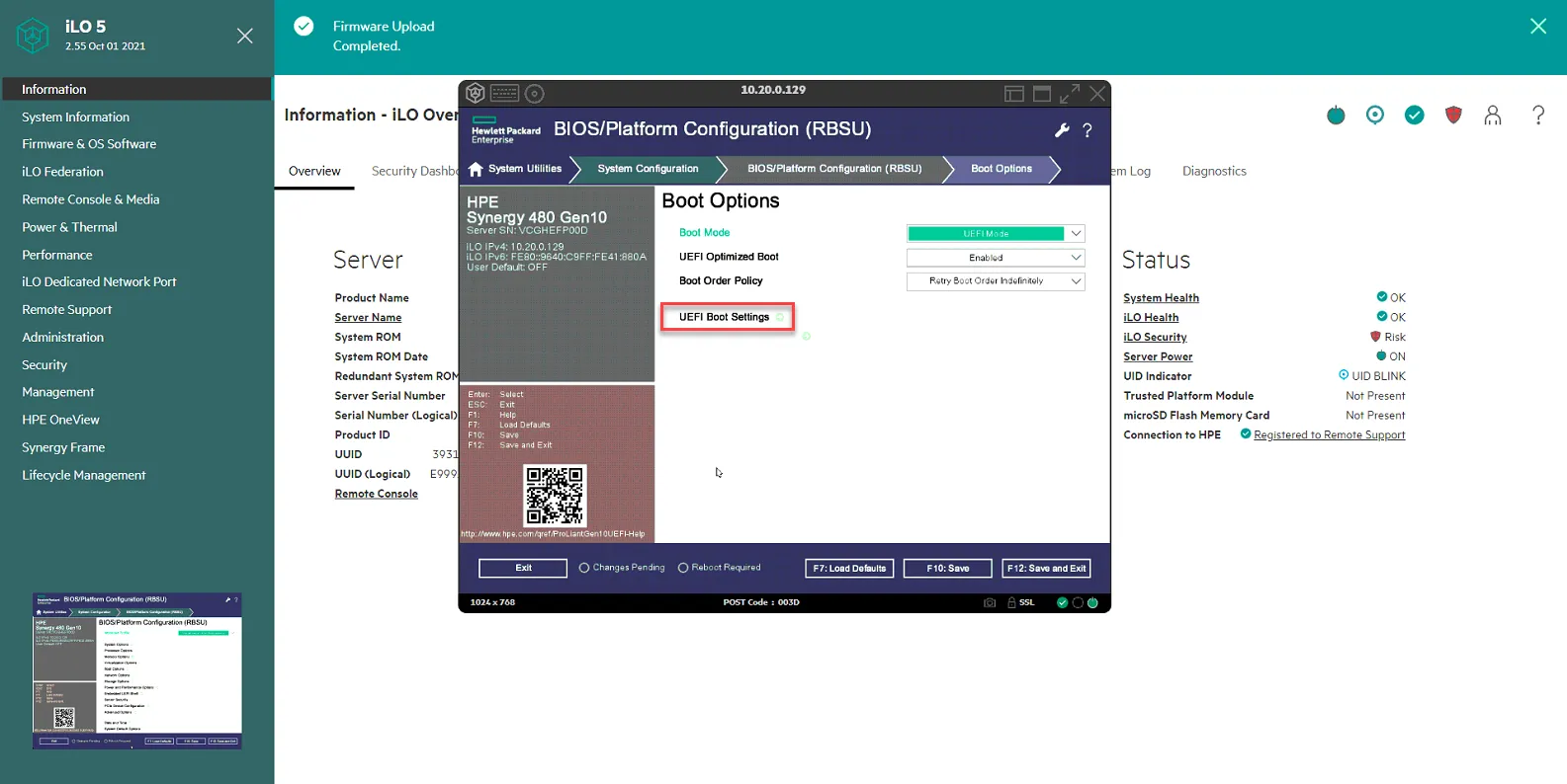
Edit Boot Order in BIOS.
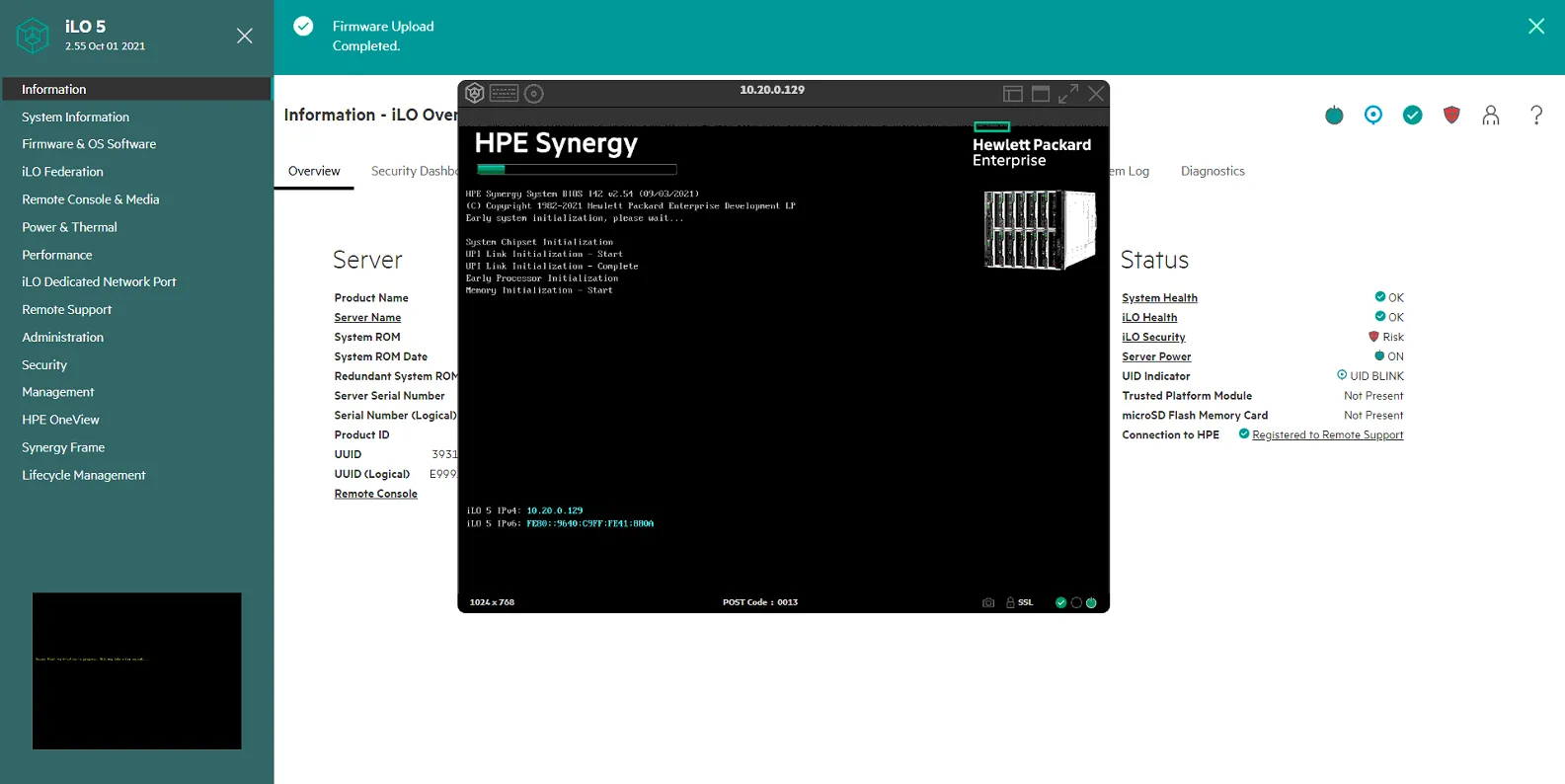
Section titled “Edit Boot Order in BIOS.”Log into iLO, and boot up server. Once server is booting, Open Console.
When prompted, select F9 to get to System Utilities. Select System Configuration.
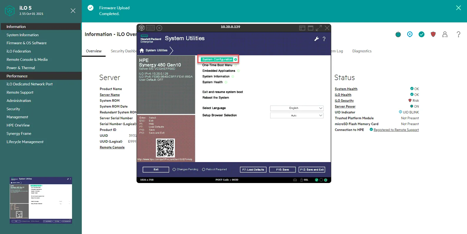
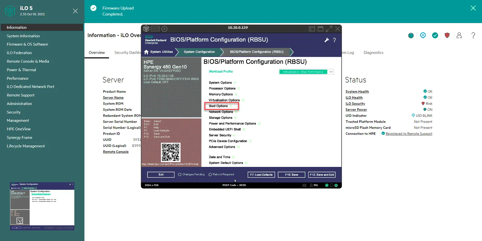
Select BIOS/Platform Configuration (RBSU)

Select Boot Options
Select UEFI Boot Mode Settings
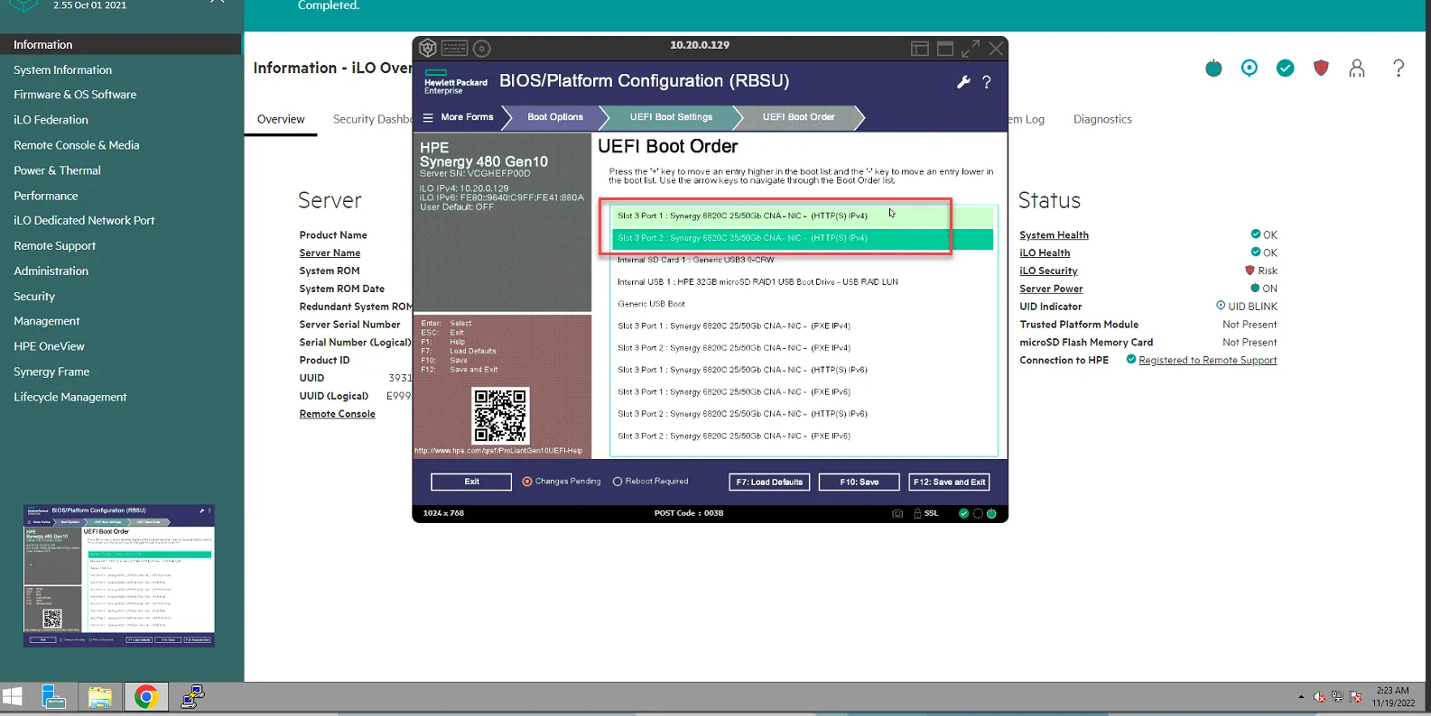
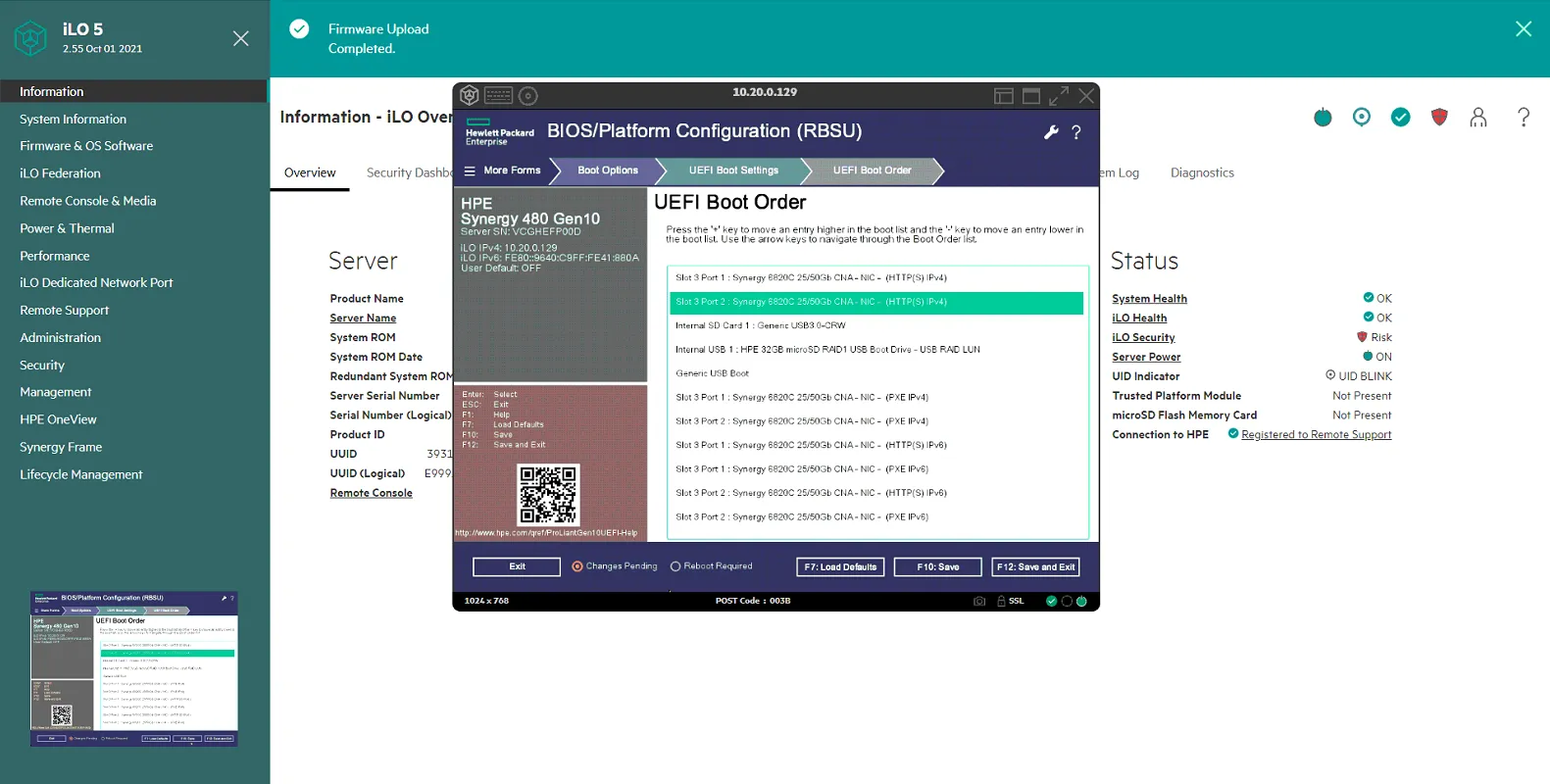
Select Boot Order.

Drag and Drop Slot 3 Port 1 HTTPS and Slot 3 Port 2 HTTPS to the very top.
Click F10: Save, then click UEFI Boot Settings.
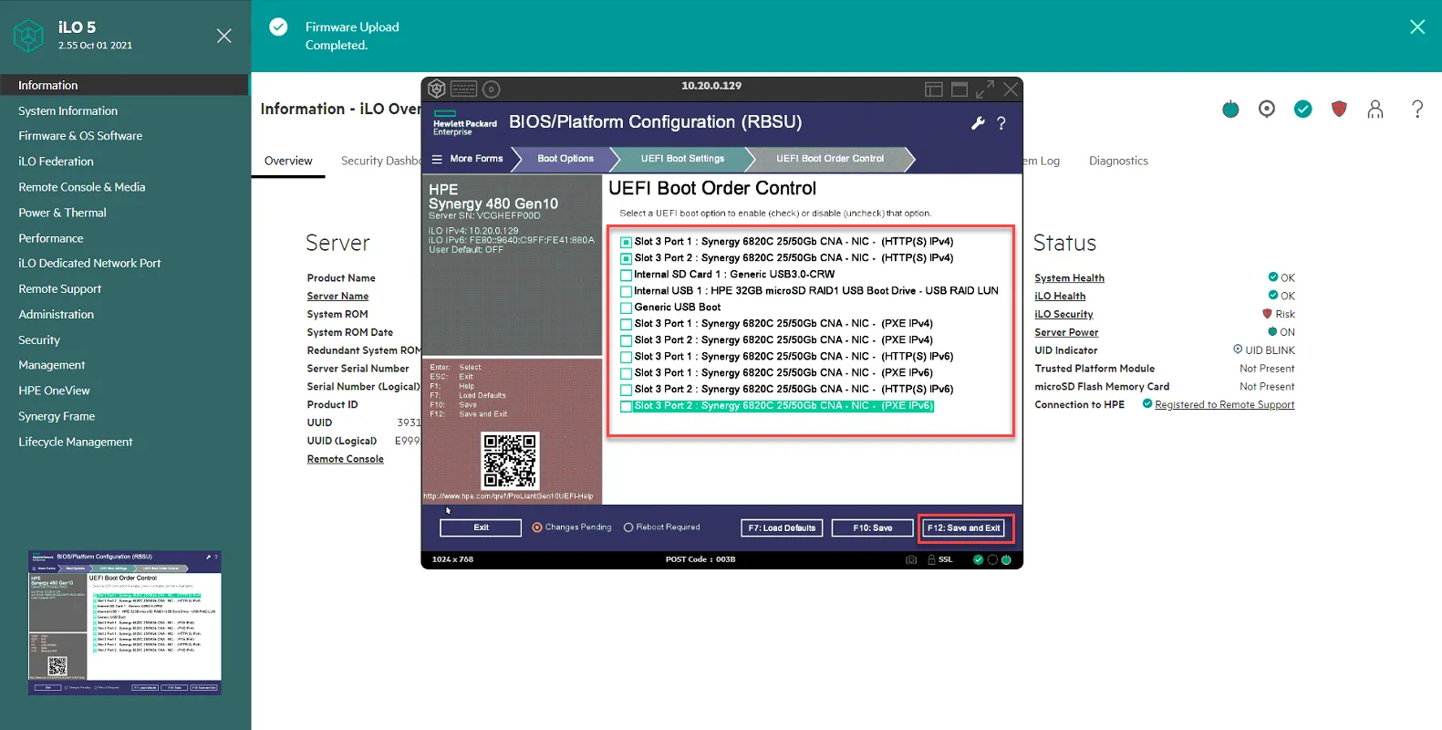
Select UEFI Boot Order Control

Uncheck ALL except Slot 3 Port 1 HTTPS and Slot 3 Port 2 HTTPS. Click F12:Save and Exit.
Install Vmware ESX 7
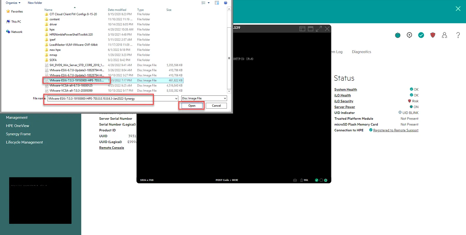
Section titled “Install Vmware ESX 7”Log into the iLO and launch the console. Click on the circular button, then select CD/DVD, then select local .iso file.
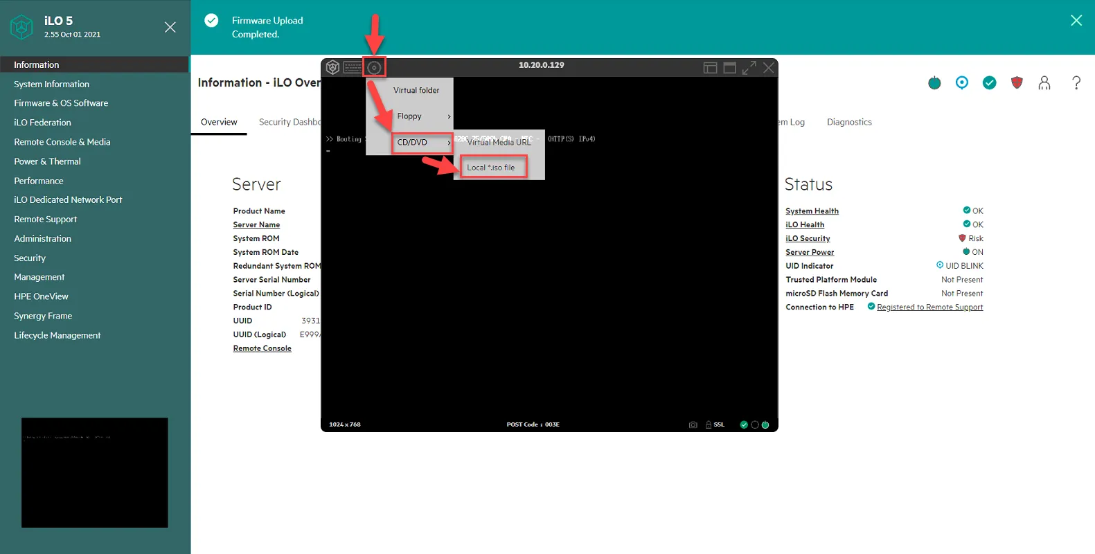
Select the vmware esxi 7 ISO from January 2022 for Synergy. Note: you can obtain this ISO from Jomer or Andy. Click Open.
Reboot Host.
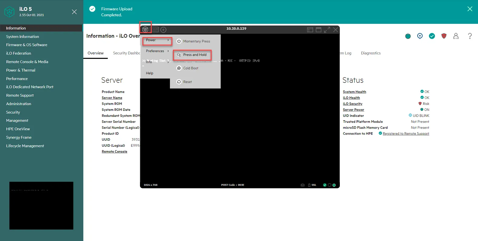
Once it is booting up, press F11 when prompted for Boot Menu.
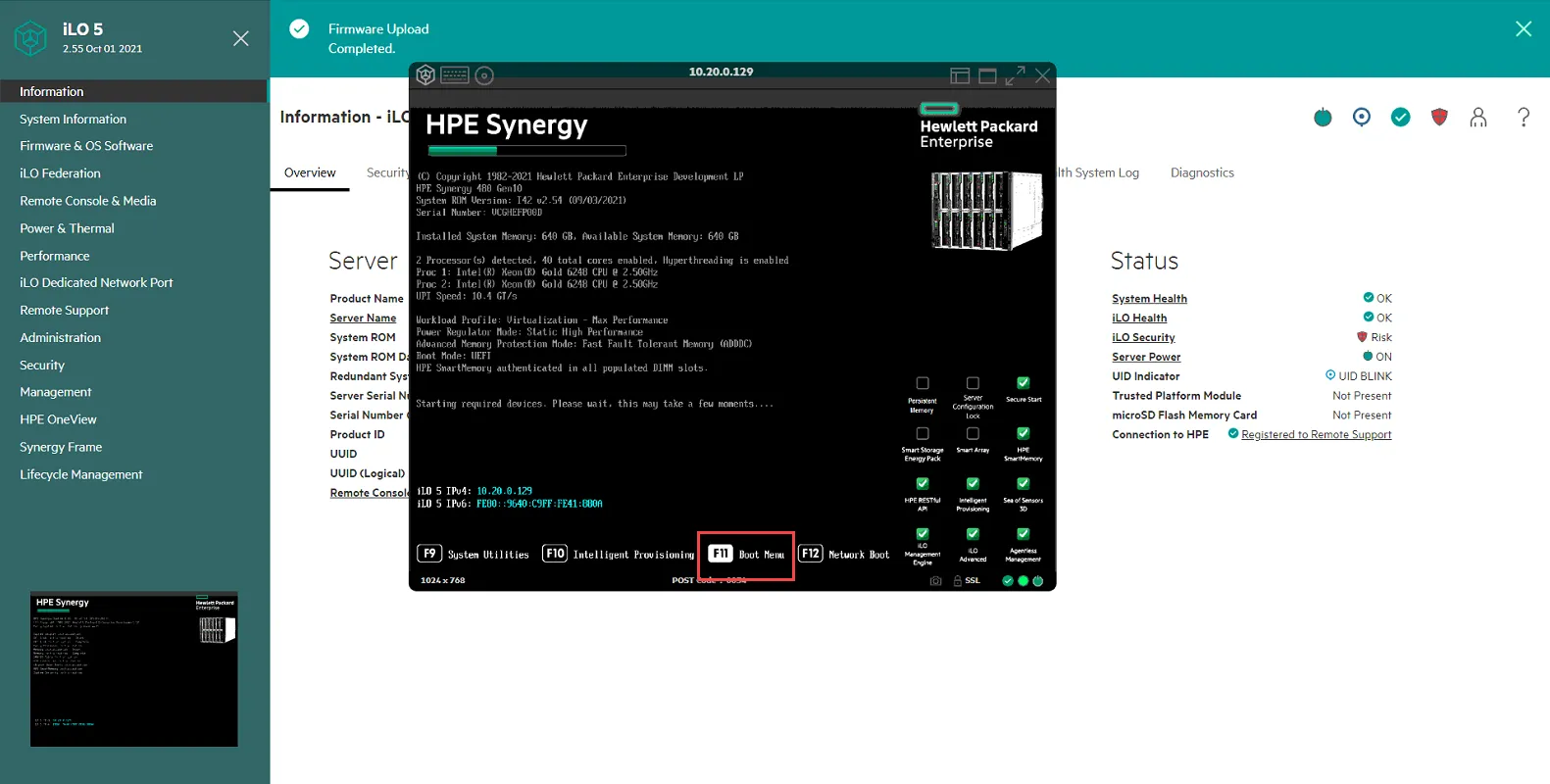
Select iLO Virtual CD-ROM
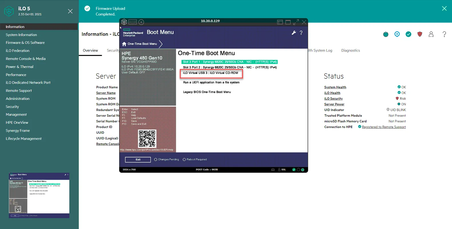
ESXi Install should start loading
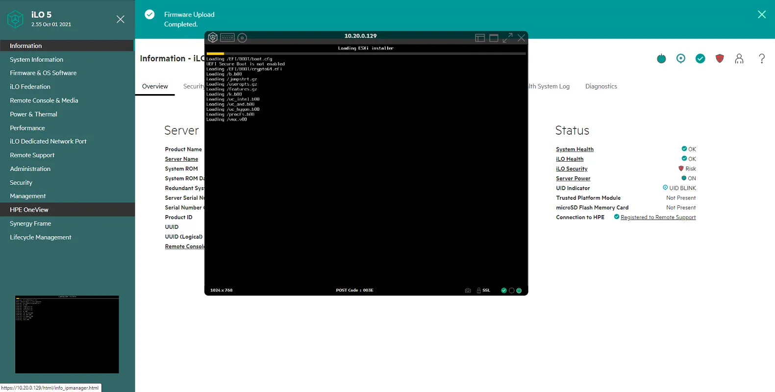
Follow the prompts to install ESXi 7
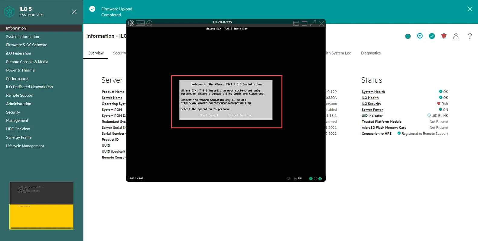
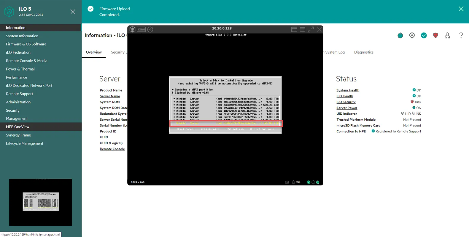
When prompted, select the 128GB partition. It will be the one without the asterisk *. Hit Enter.
Set Admin Password. Use password specified in pwstate.
Confirm Install by pressing F11.
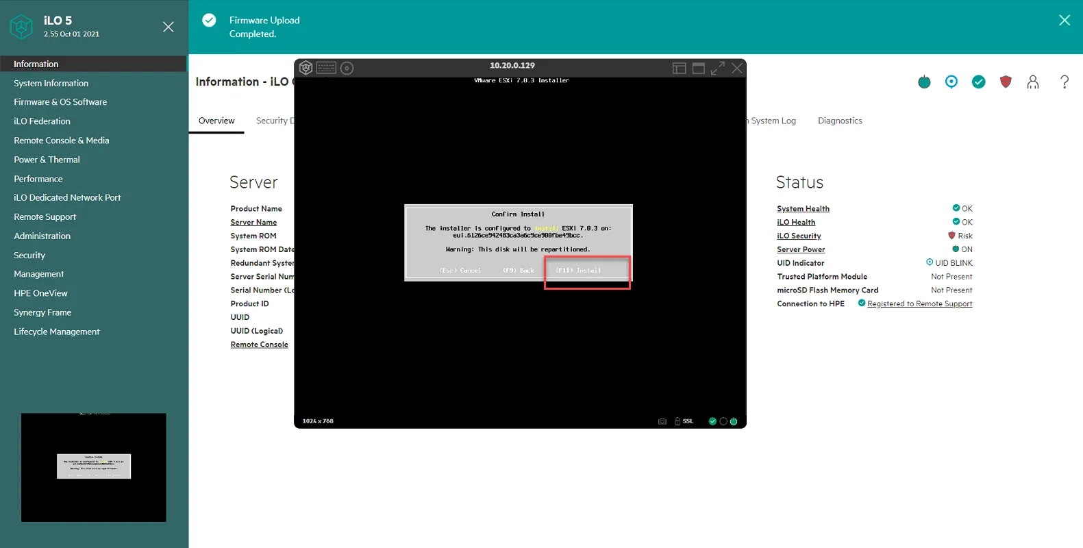
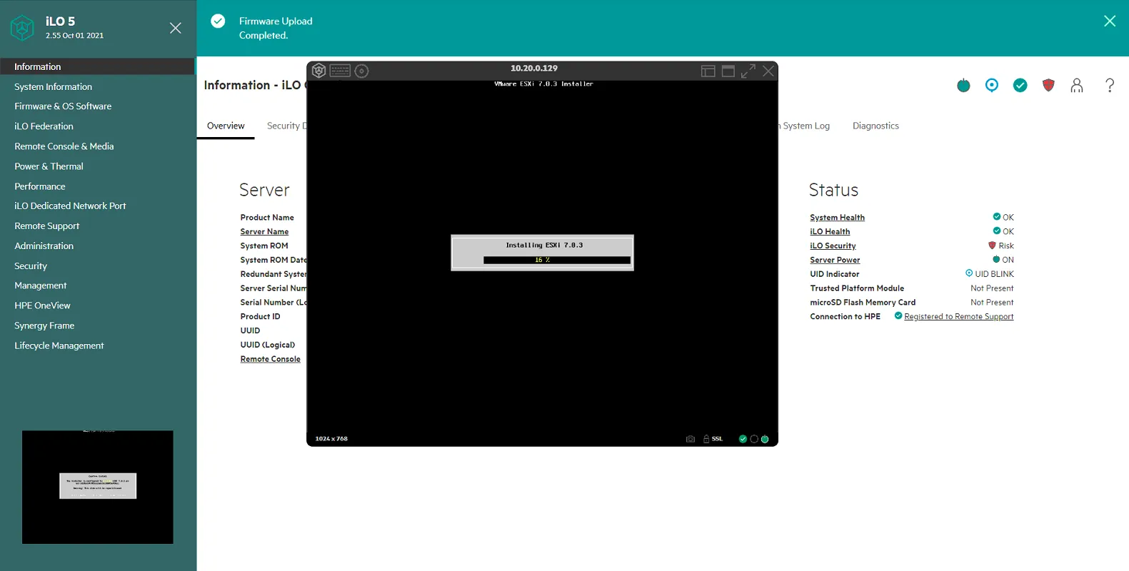
Install will commence.
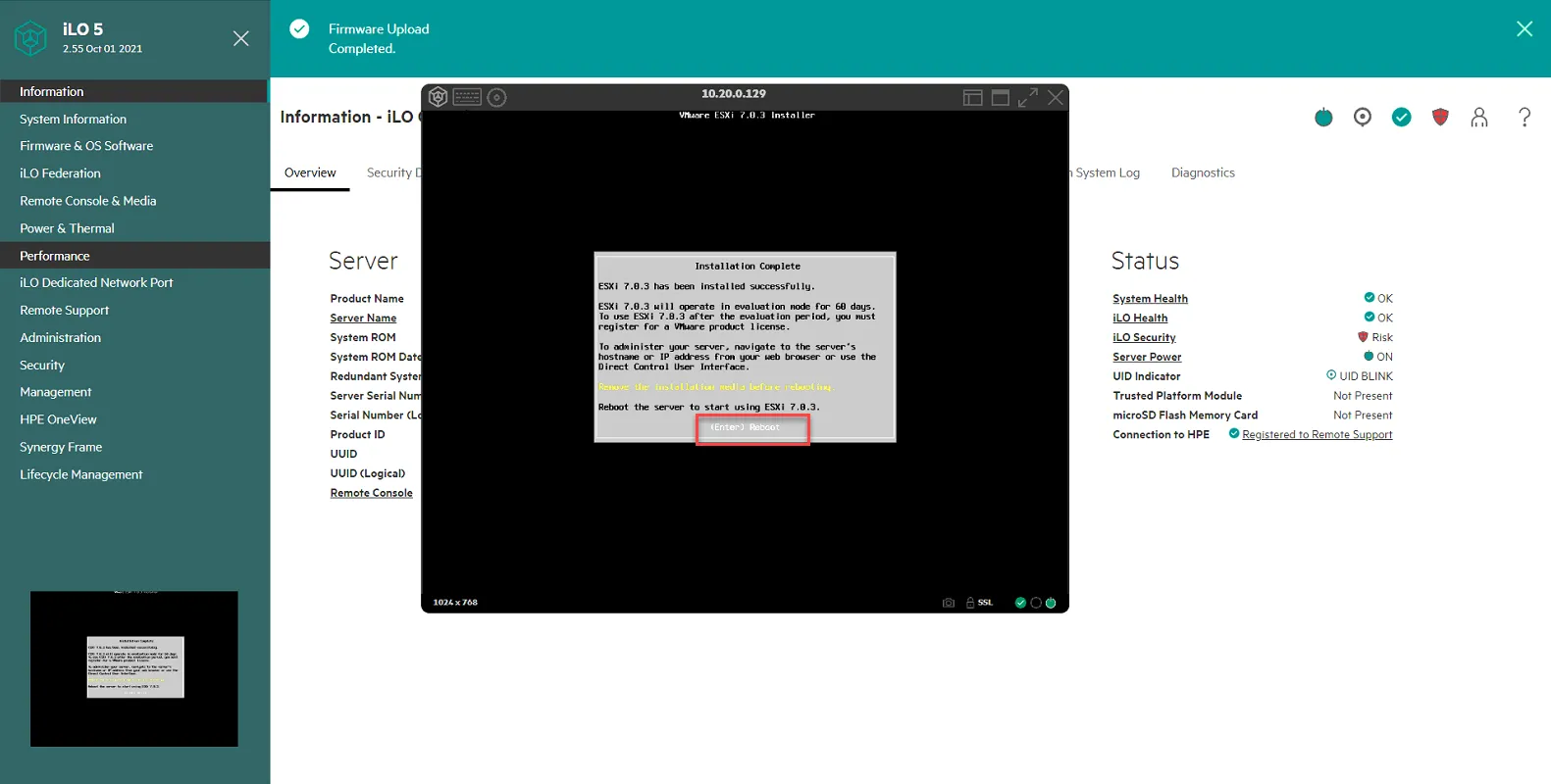
Once the install is done, press Enter to reboot.
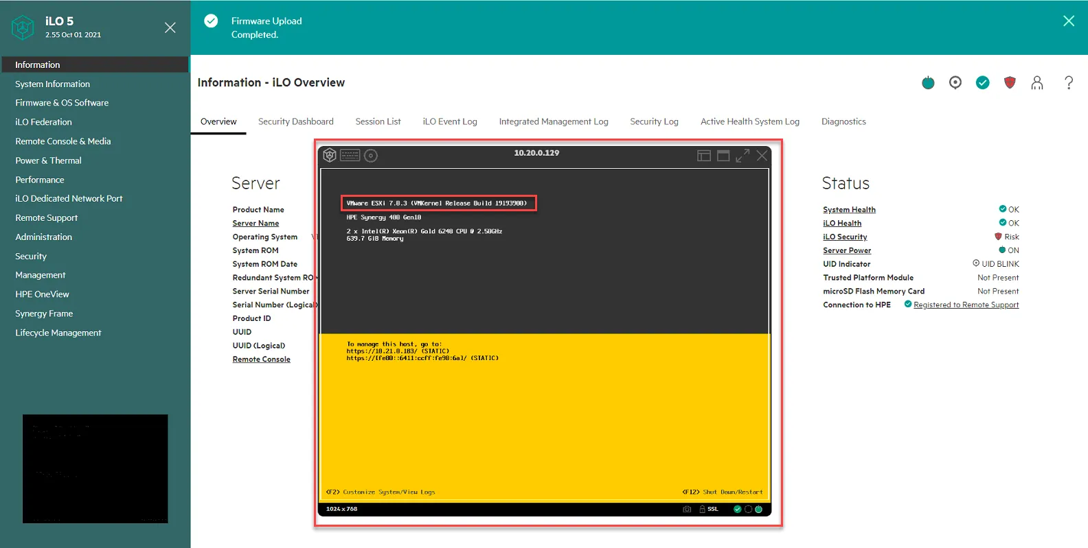
CONGRATULATIONS! VMWARE ESX 7.0 IS INSTALLED ON THE SERVER!!! But wait, there’s more…
Update Bootbank file to fix issue with configuration changes not saving
Section titled “Update Bootbank file to fix issue with configuration changes not saving”If you notice the ESXi host now boots up with the ISCSI-A IP address as its management. If we try to update the config, we will lose the settings once we reboot. To fix this, we follow the instructions outlined in this VMware KB article:
https://kb.vmware.com/s/article/2149444
Log into NFINIT-VPROXY1 since it can communicate with the ISCSI-A and ISCSI-B VLAN. From there, launch the browser and go to the management IP on your ESX7.0 host. Log in with the root creds you created.
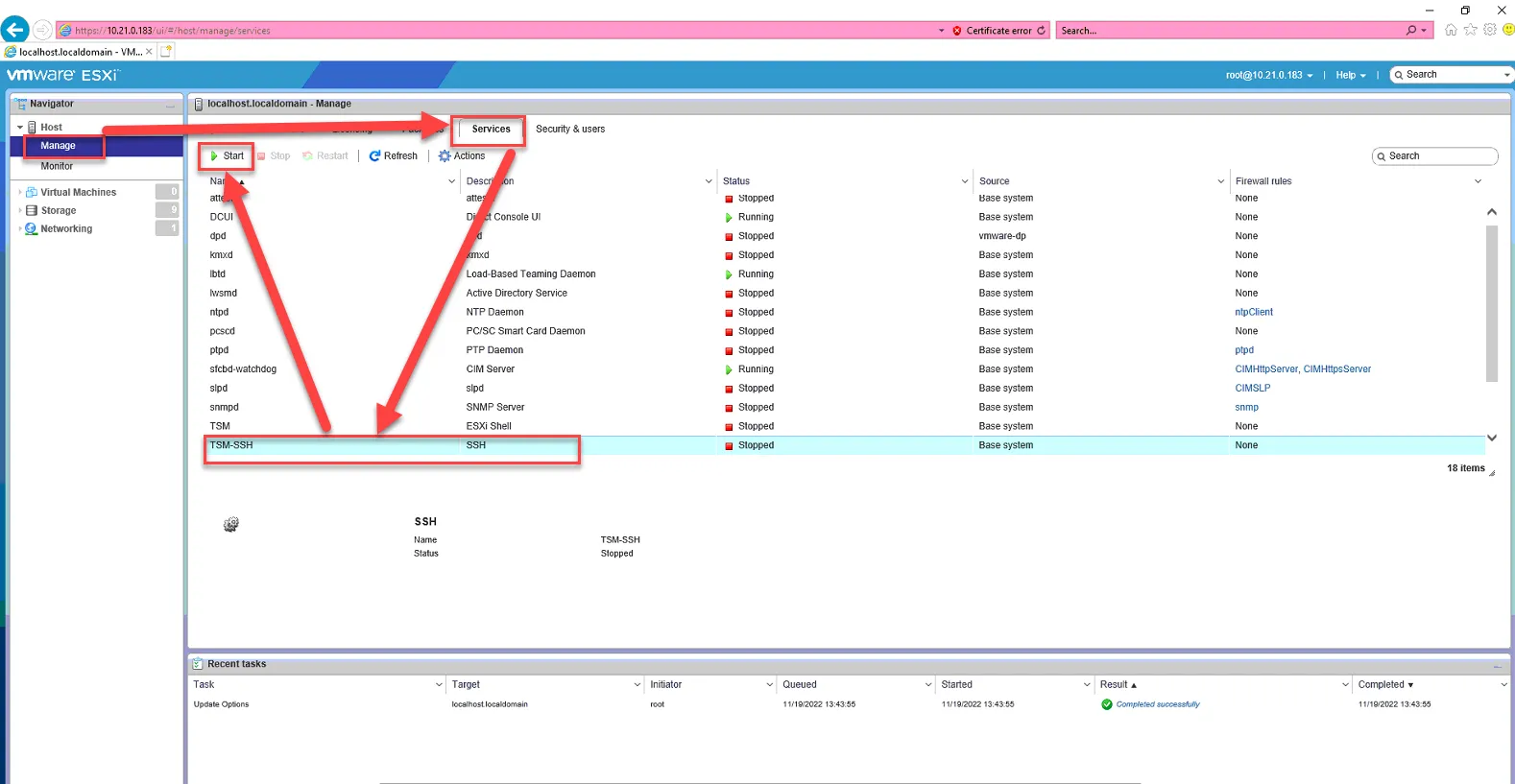
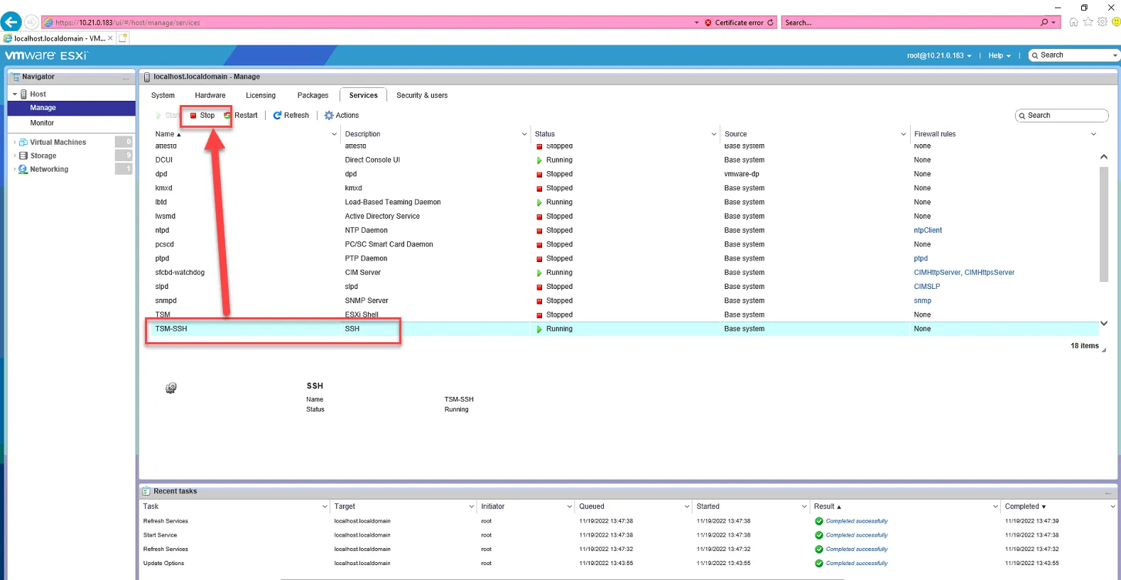
Enable SSH by going to Manage, then Services, select TSM-SSH, and select Start.
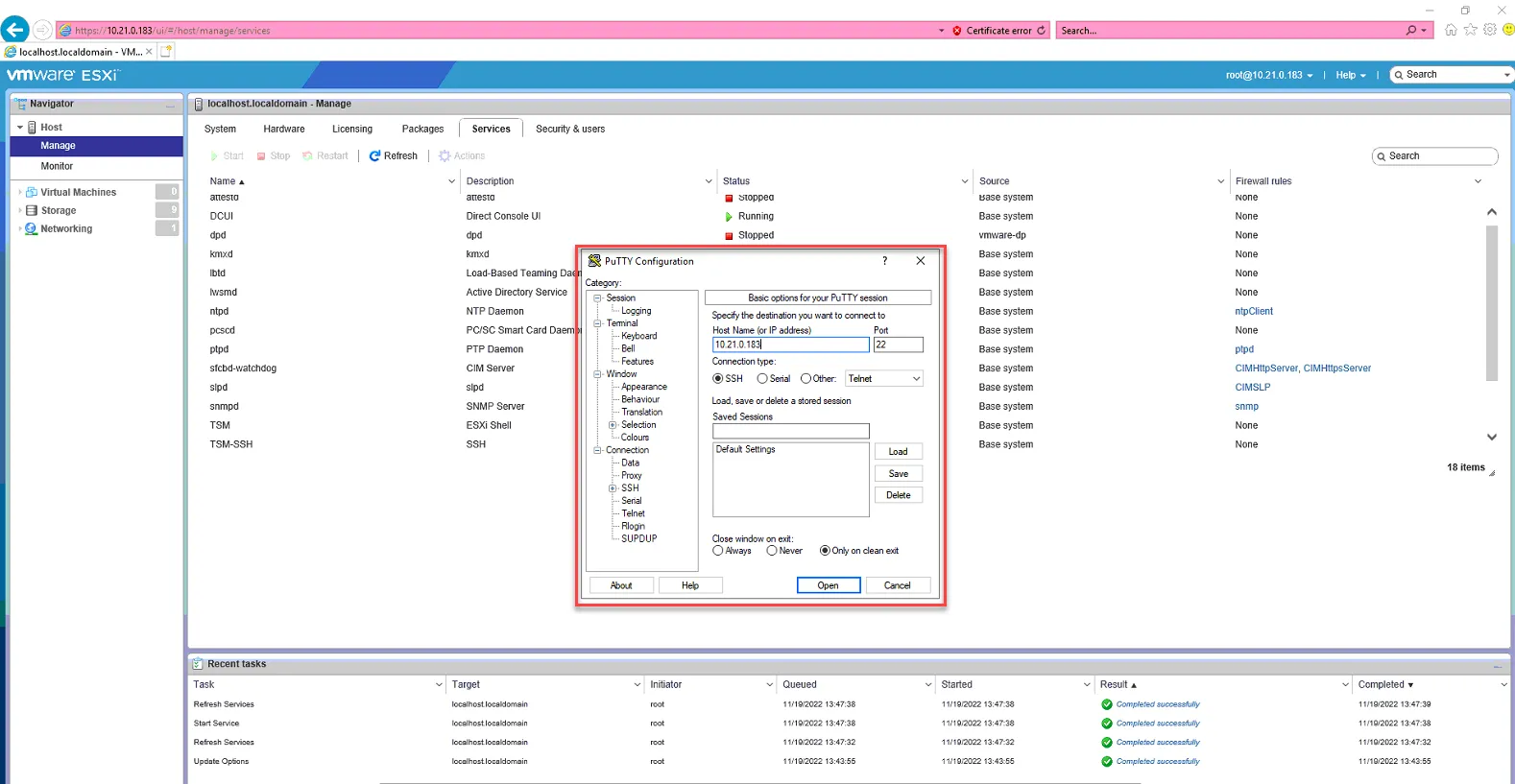
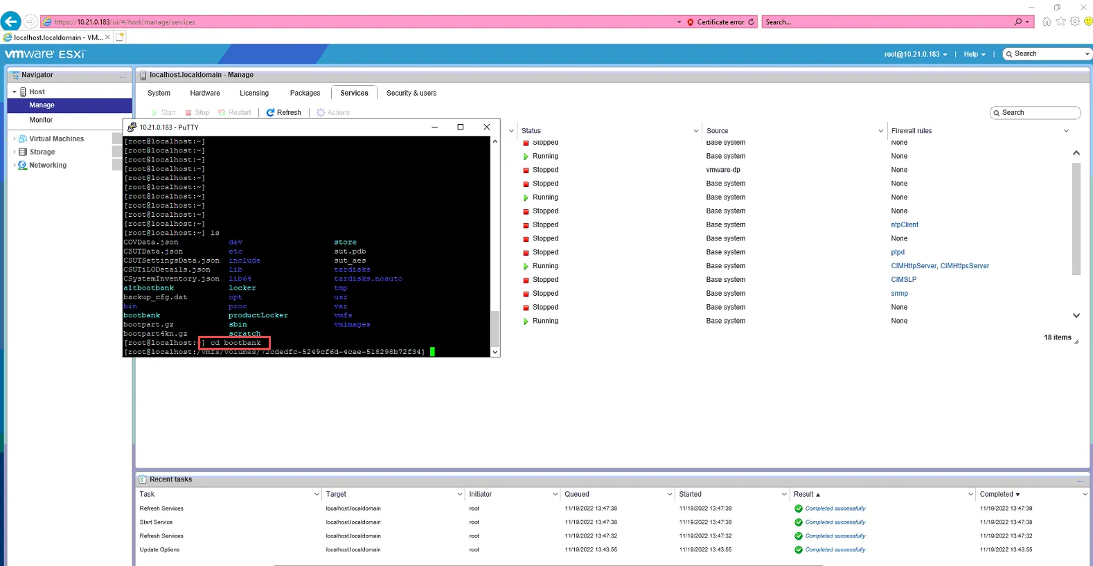
Open Putty, and SSH to the ESXi7 host.
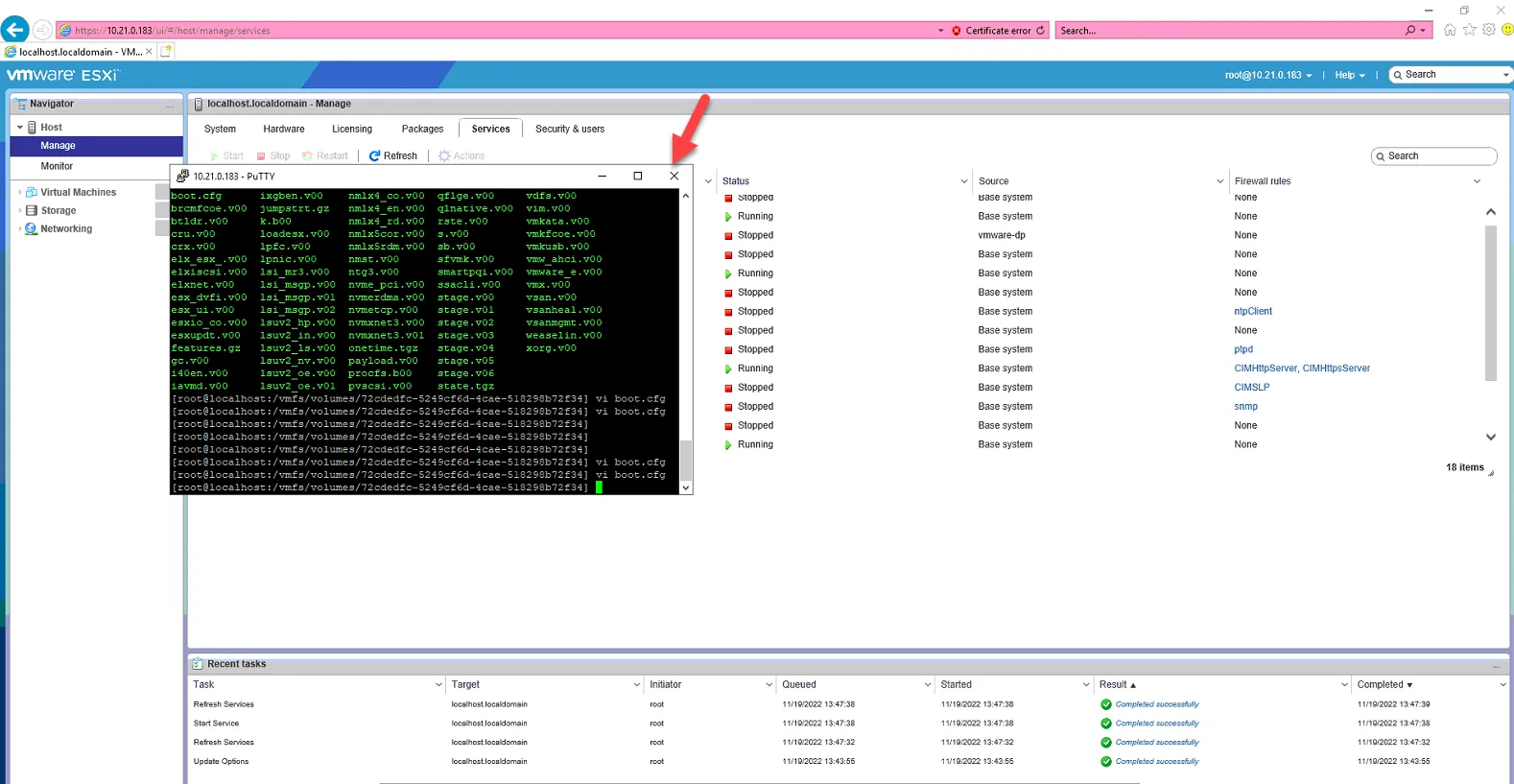
Once you are logged in via putty, type in “ls” in the command prompt, and press enter. You should see bootbank listed below.
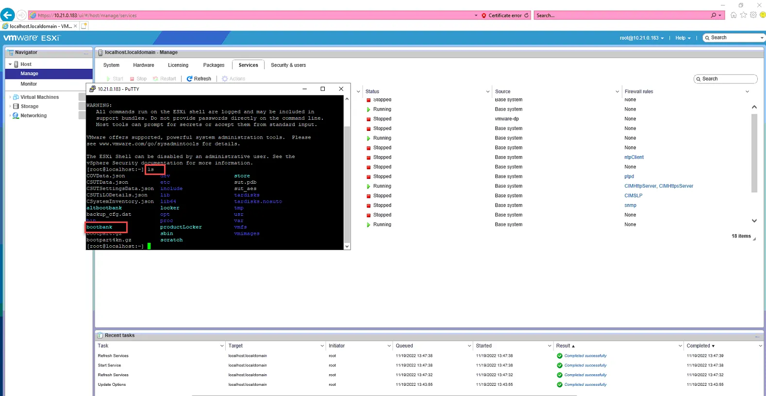
Type in “cd bootbank” and press enter to go into the bootbank directory.
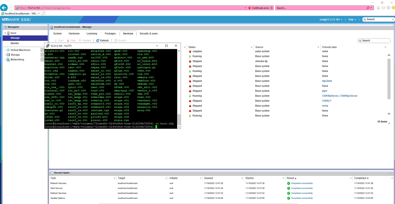
Type in “vi boot.cfg” to open the text editor to edit the boot.cfg file.
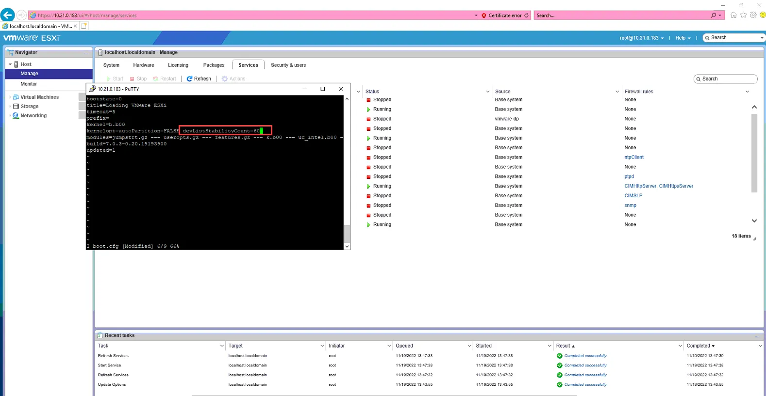
Press “I” (capital i) to go into Insert mode. Scroll the green cursor to the end of “kernelopt=autoPartition=FALSE” and type the space bar.

The type in “devListStabilityCount=60”
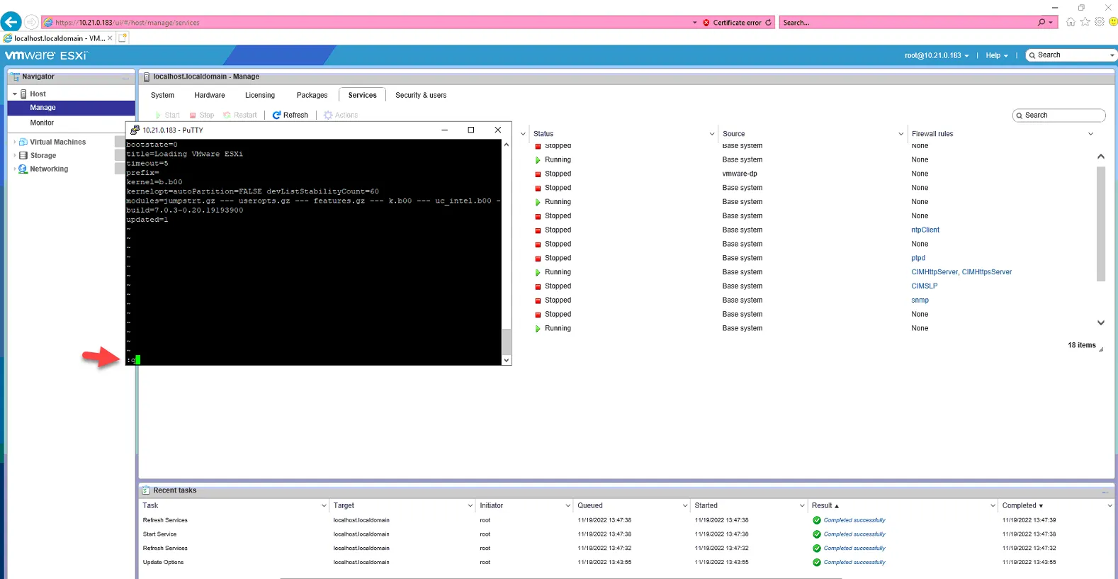
Hit Esc key to get out of insert mode, then type ":w" and hit enter to save the changes to the boot.cfg file.

Then type in ":q" to quit the editor screen.
You can now close out of the putty session.
Stop the SSH Service.
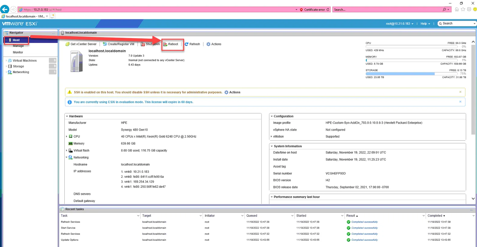
Reboot the host.
Configuring Network Settings on the host
Section titled “Configuring Network Settings on the host”First we’ll add ISCSI-B so that the next time we boot, it can boot from ISCSI-B since we are changing management.
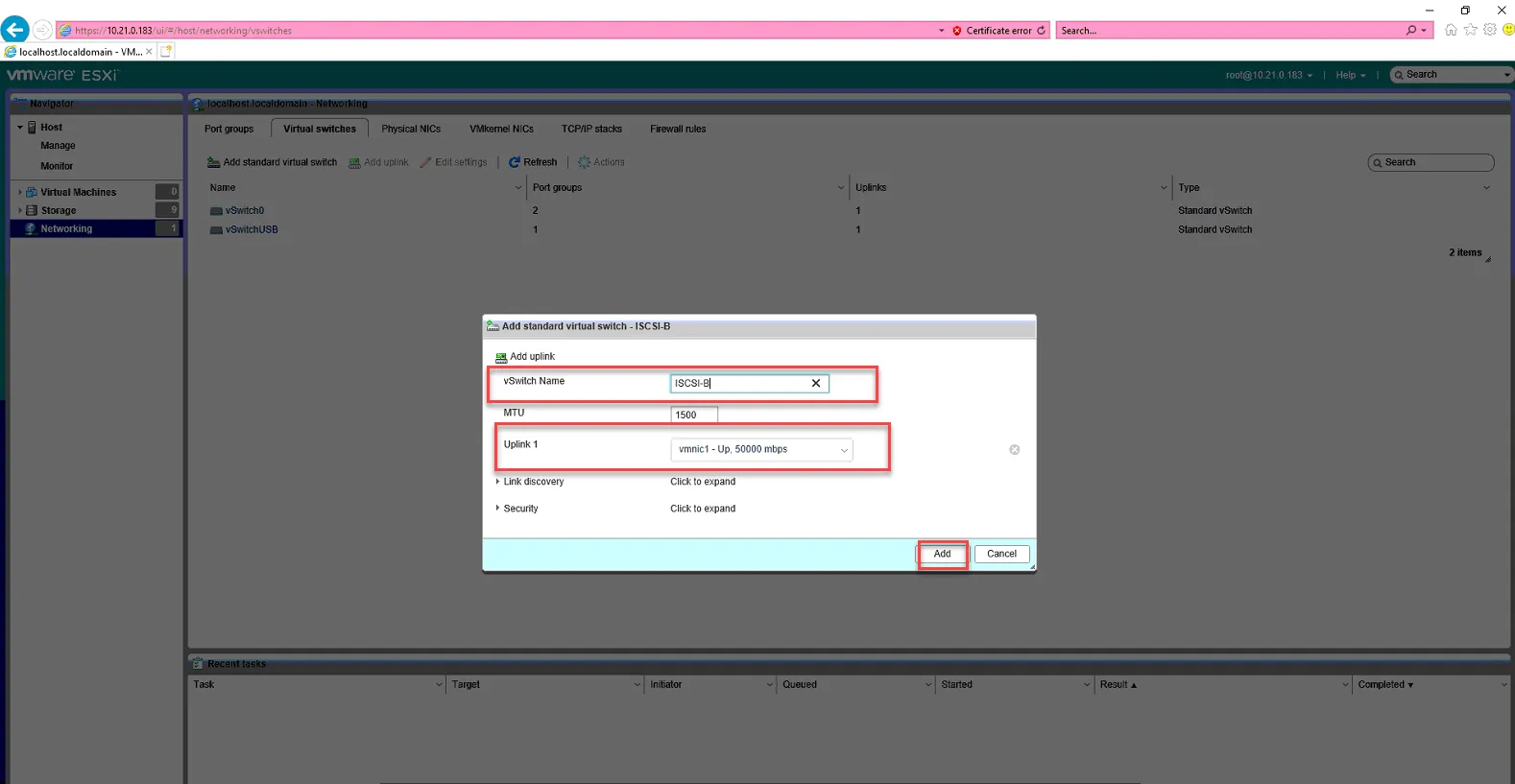
Log back into the host. Go to Networking. Go to Virtual Switches. Click Add standard virtual switch.
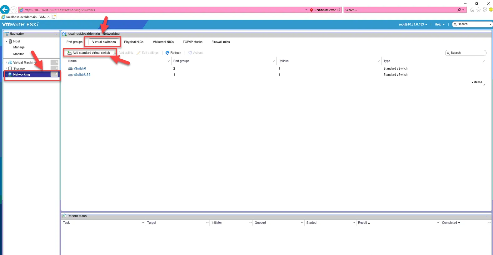
Name: ISCSI-B
Uplink: nmnic1
Click Add
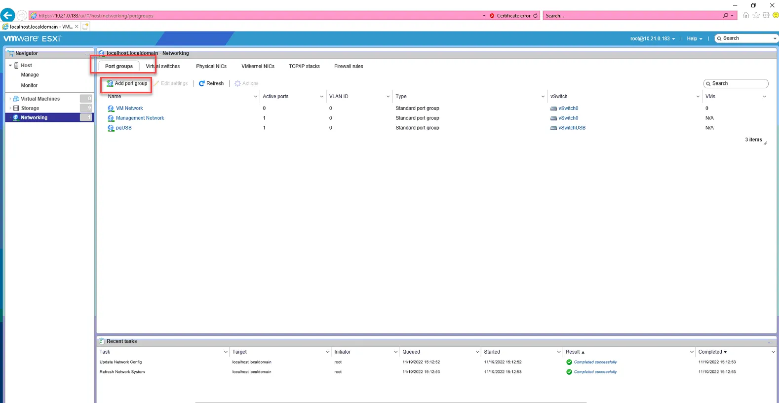
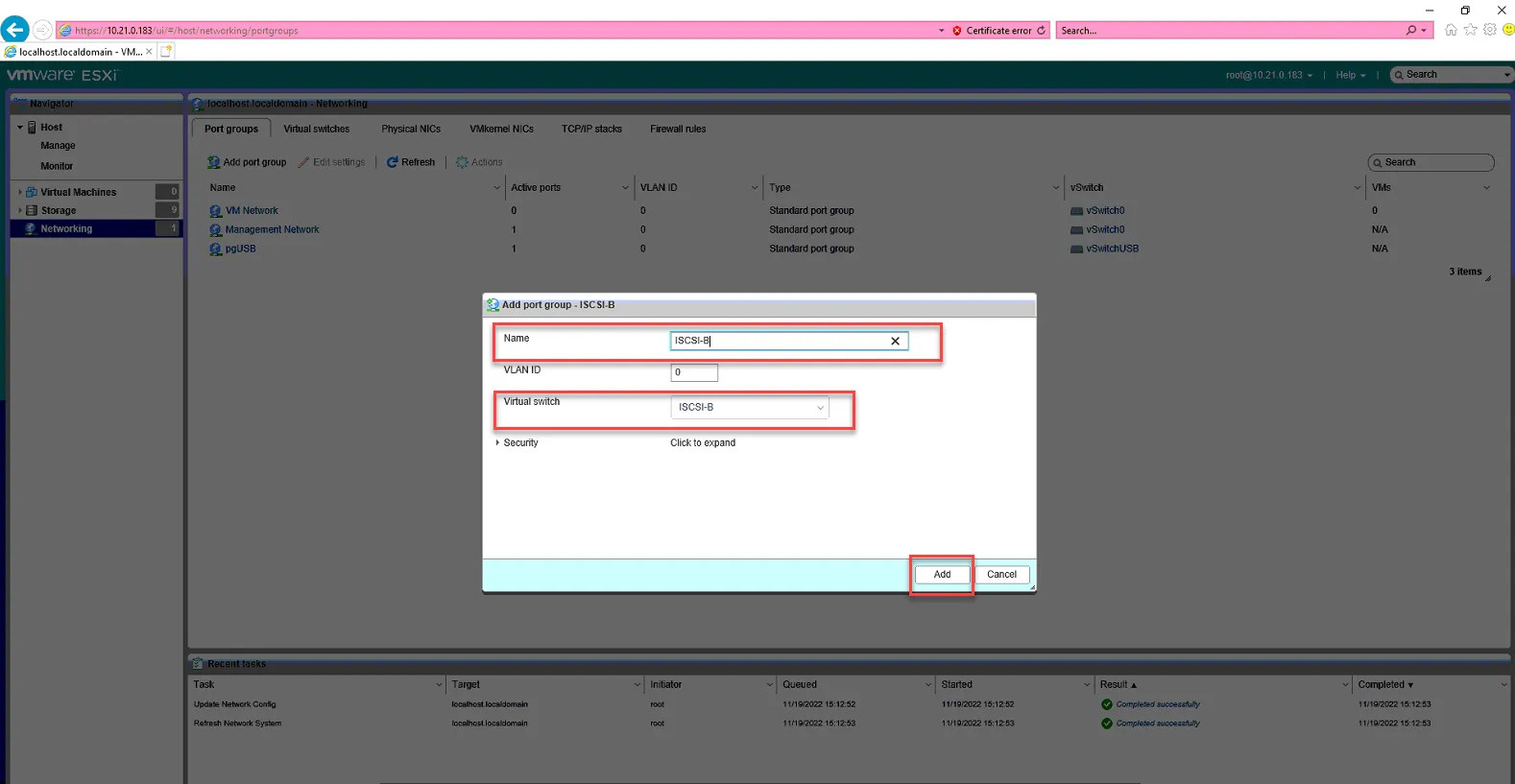
Go to Port Groups, Click Add Port Group.
Set name to ISCSI-B
Set virtual switch to ISCSI-B. Click Add
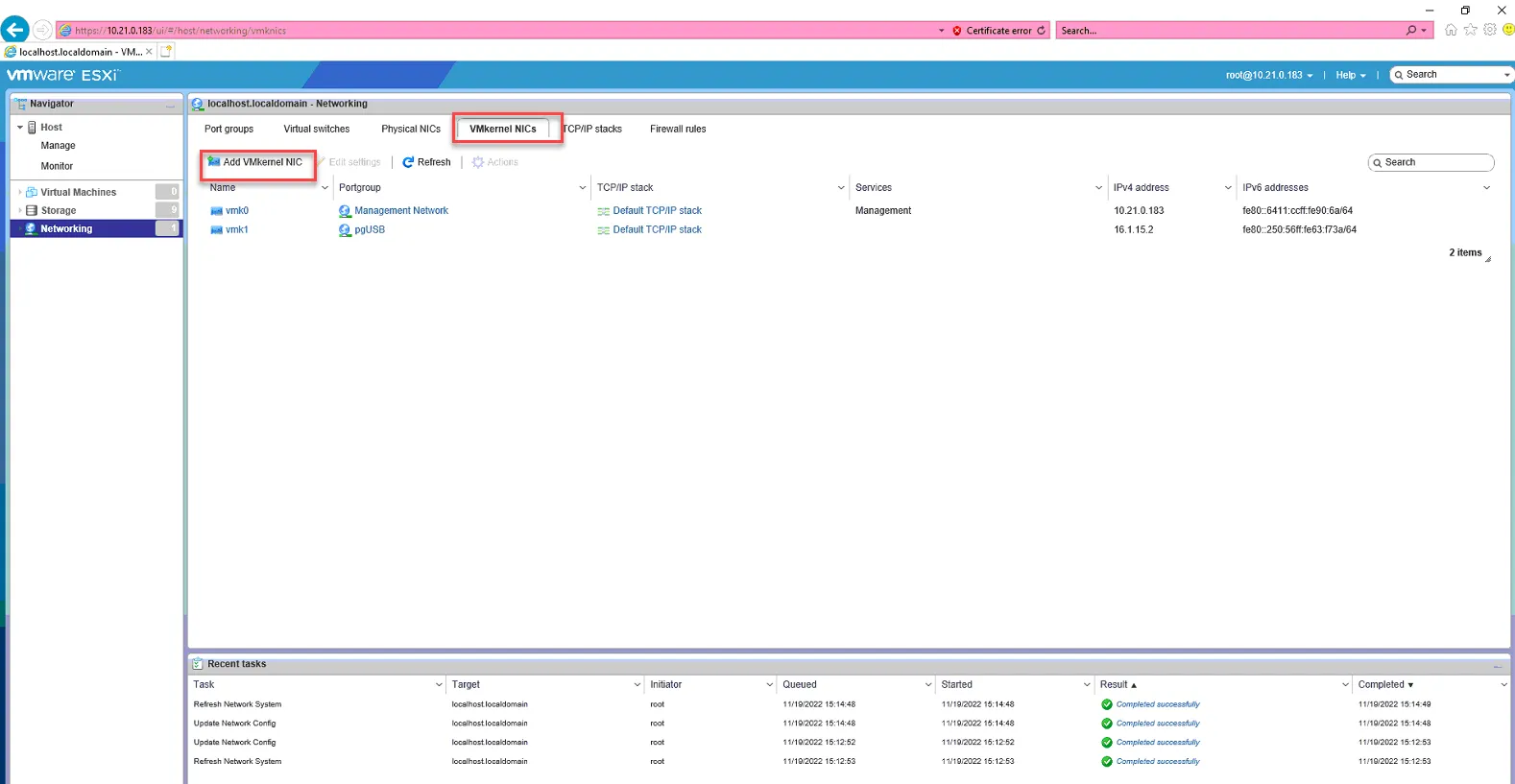
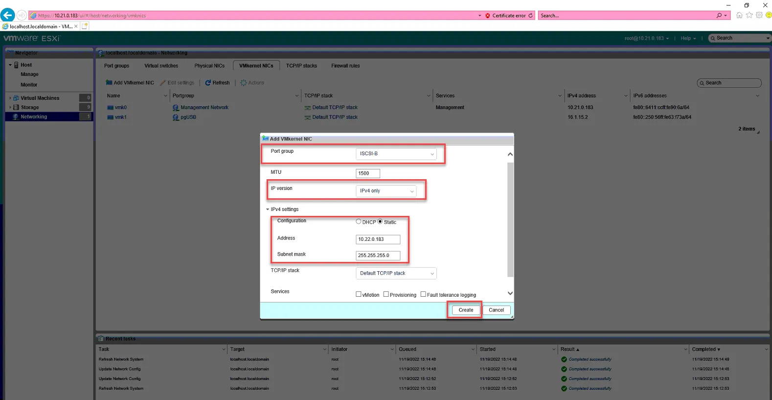
Go to VMkernel NICs, click Add VMkernel NIC.
Set Port Group to ISCSI-B
IP Version - IPv4 Only.
Expand IPv4 Settings and set it to Static
Address is: 10.22.0.x where x = the IP of the host. In this example, we are setting it to 10.22.0.183 since it is ESX-4.
Click Ok
ISCSI-B is now set up. Proceed with setting up vMotion.
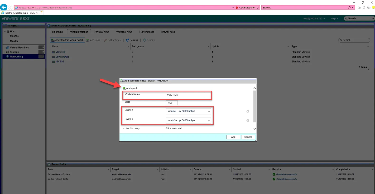
To set up vMotion, click Virtual Switches, Click Add standard virtual switch.
vSwitch Name: VMOTION
Click Add Uplink
Uplink1 - vmnic4
Uplink2 - vmnic5
Click Add
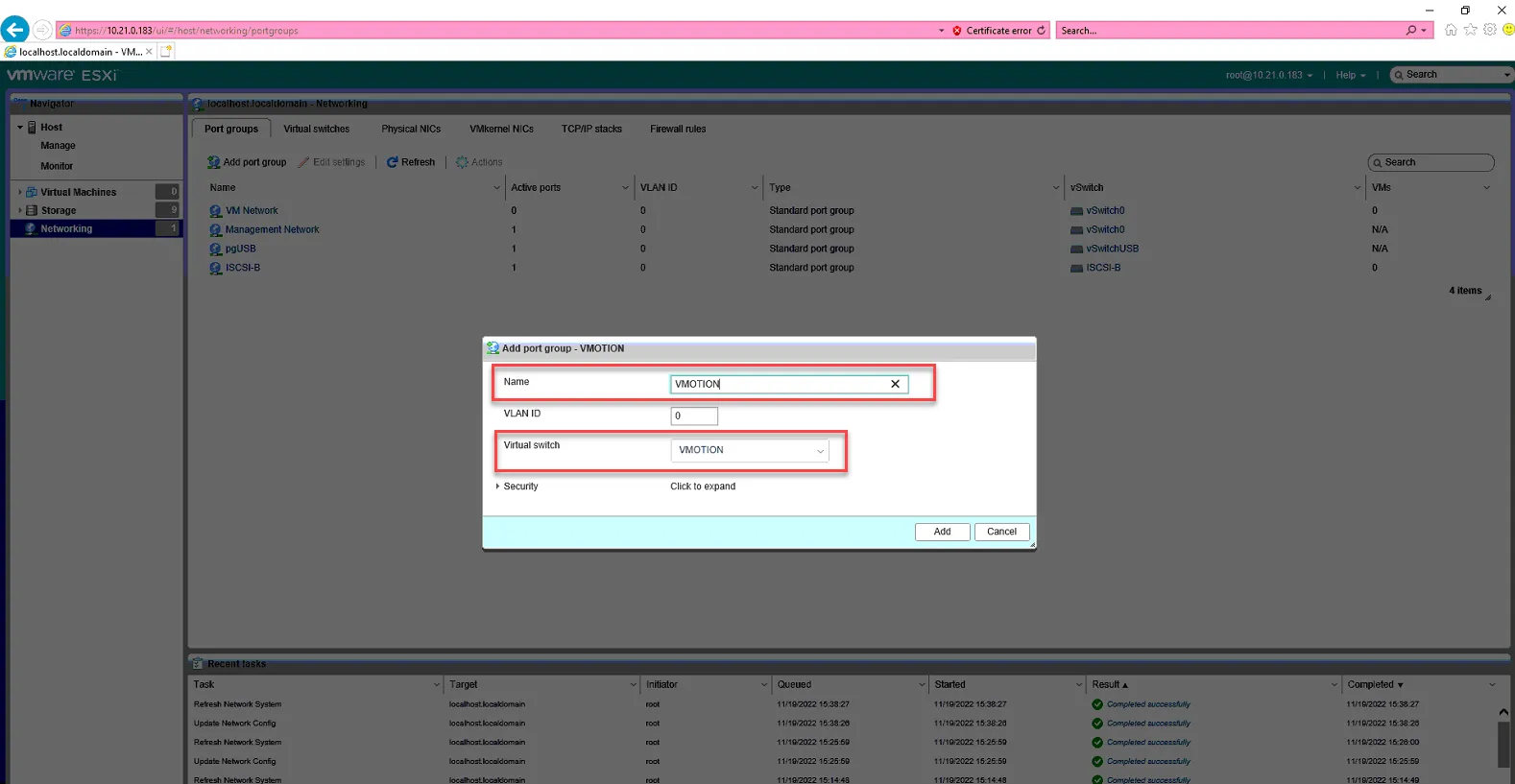
Click Port Groups, click Add Port Group
Name: VMOTION
Virtual Switch: VMOTION
Click Add.
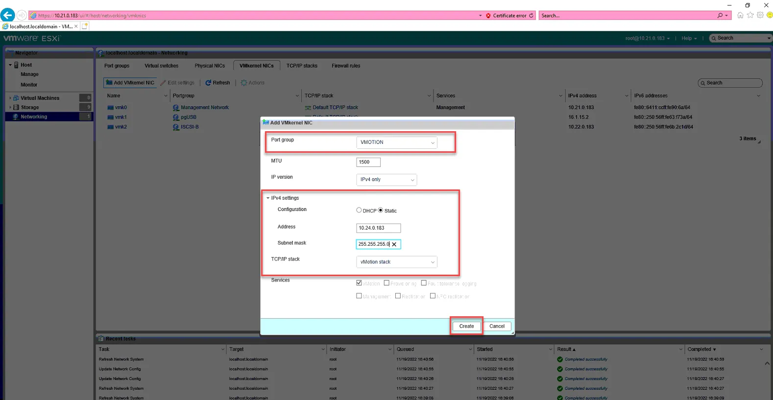
Click VMkernel NICs, click Add VMkernel NIC
Port Group: VMOTION
IPv4 Settings Static
Address: 10.24.0.x, where x is the IP of the host. In this examply we use 10.24.0.183 since .183 is the IP of ESX-4.
Subnet mask 255.255.255.0
TCP/IP Staic - vMotion Stack
Click Create.
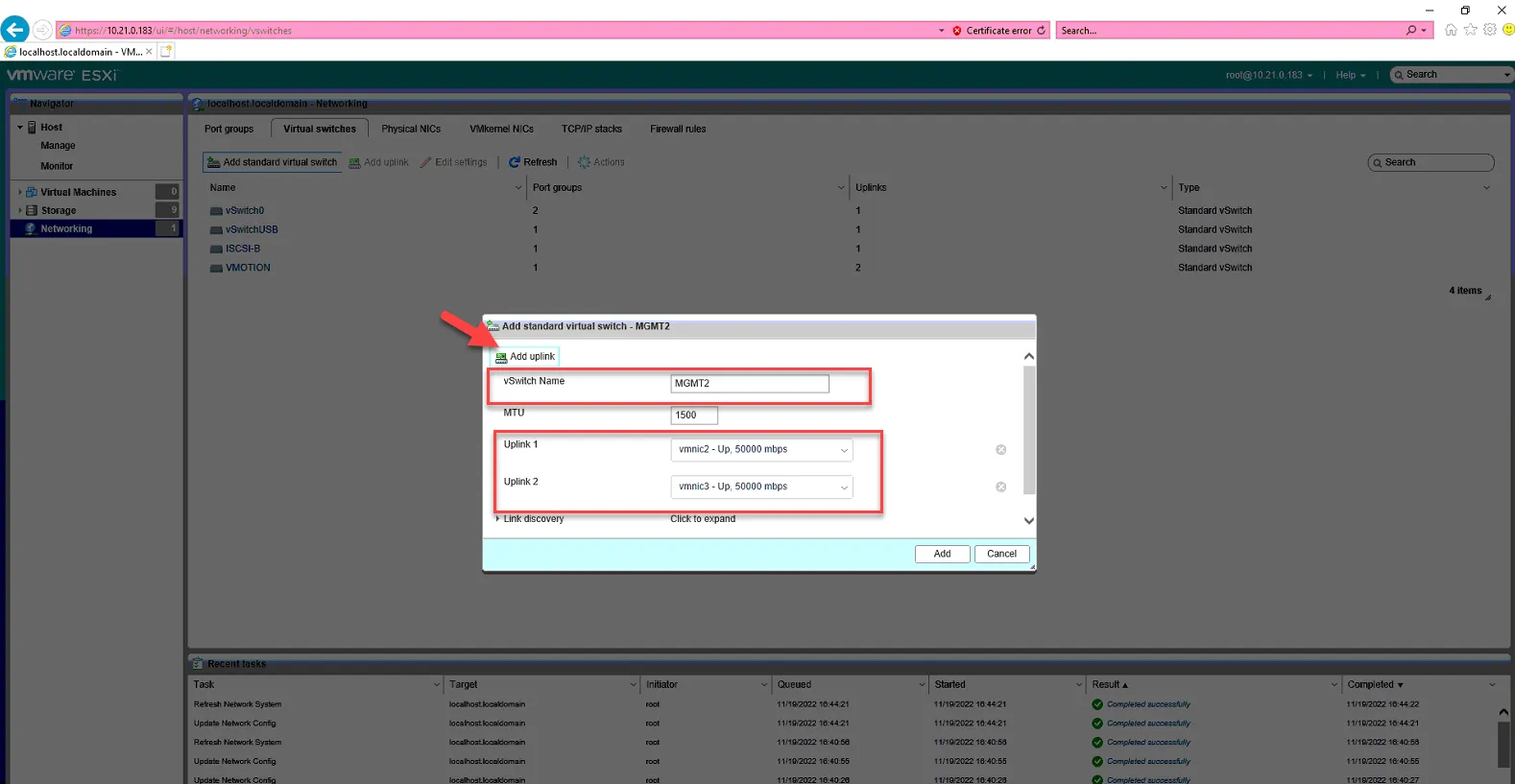
vMotion is now configured. We’ll move on to MGMT2. Click Virtual Switches, Add Virtual Switch.
vswitch name: MGMT2
Click Add Uplink
Uplink1 - vmnic2
Uplink2 - vmnic3
Click Add.
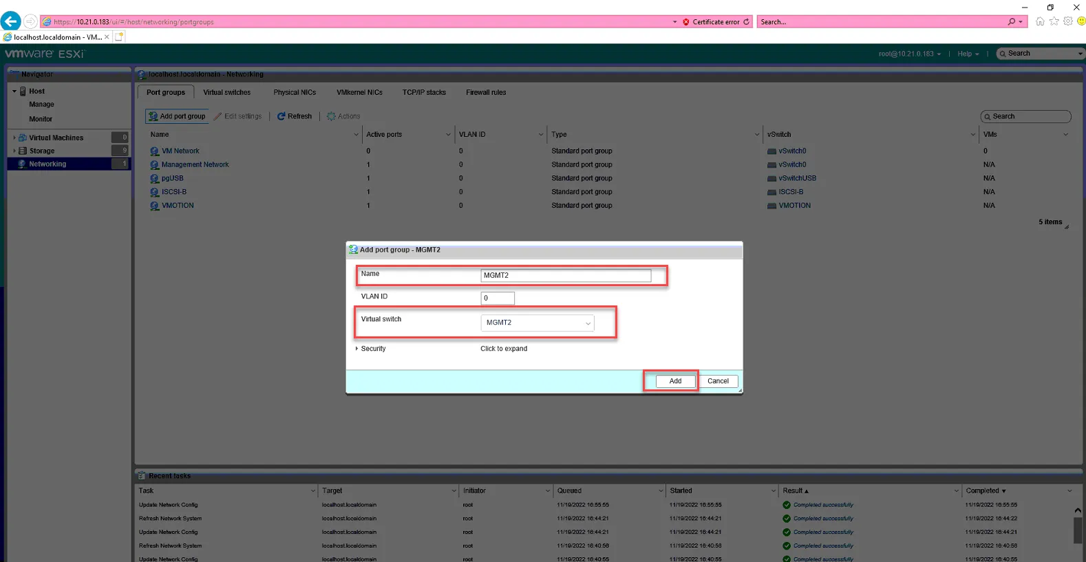
Click Port Groups, click Add PortGroup
Name: MGMT2
Virtual Switch: MGMT2
Click Add
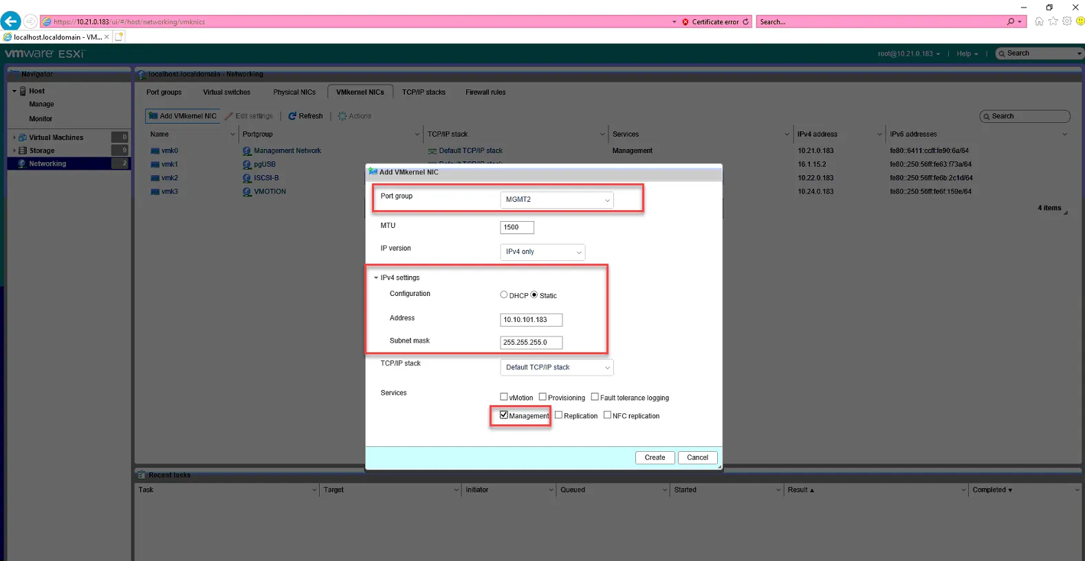
Click VMKernel NICs, click Add VMkernel NIC.
Port Group: MGMT2
IP Static: 10.10.101.x, where X is the IP of the host.
Check box for Management.
Click Create.
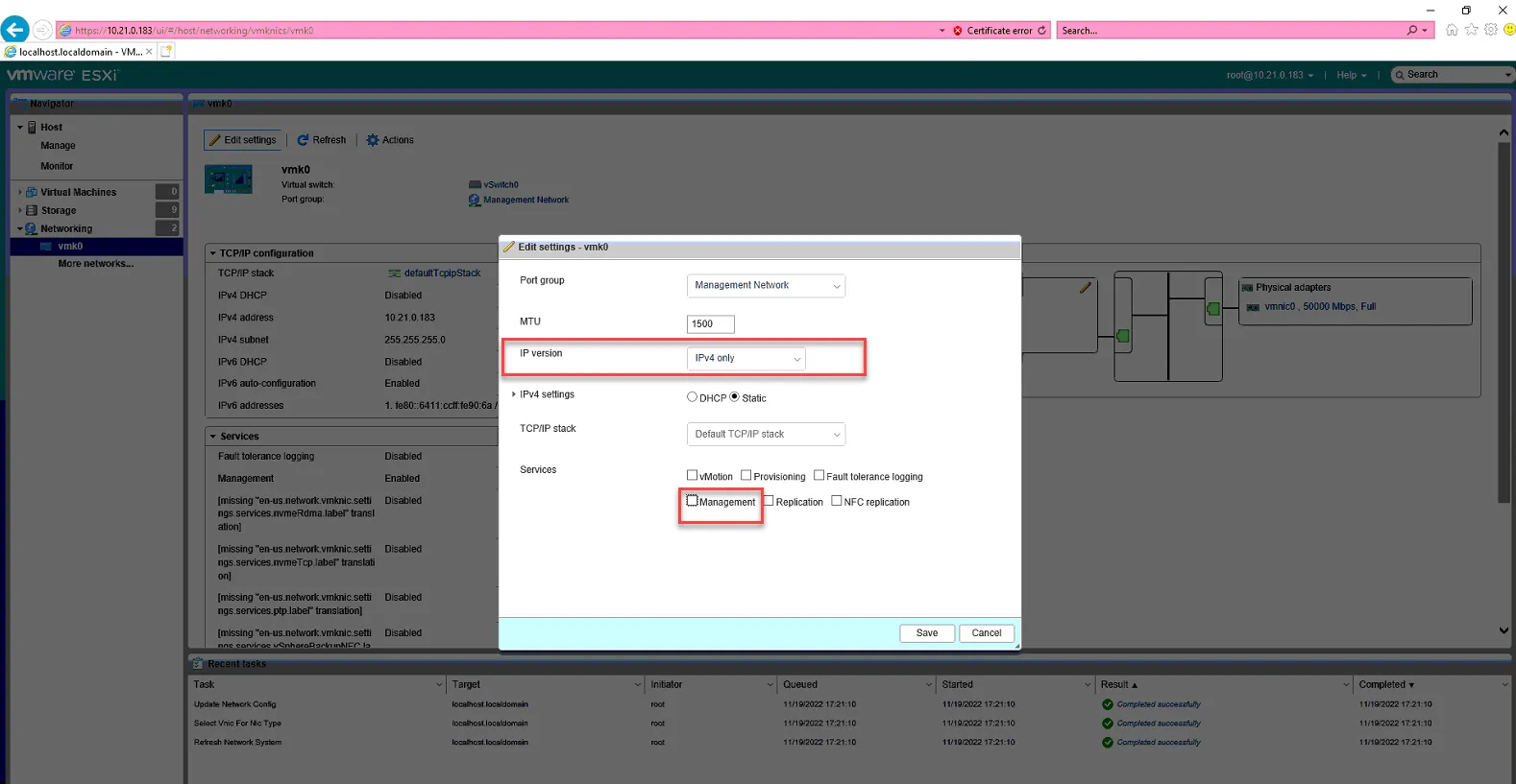
MGMT2 is now set up. Now we need to uncheck Management from our vmk0 Management Network VMkernel NIC to remove the 10.21.0.x IP from current management.
Click vmk0.
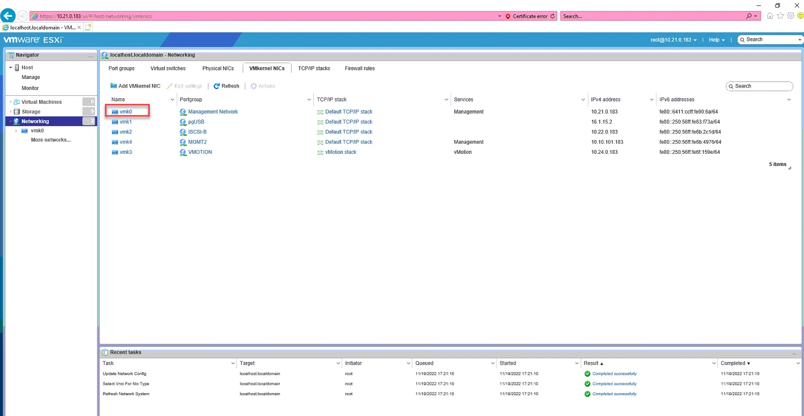
Click Edit Settings
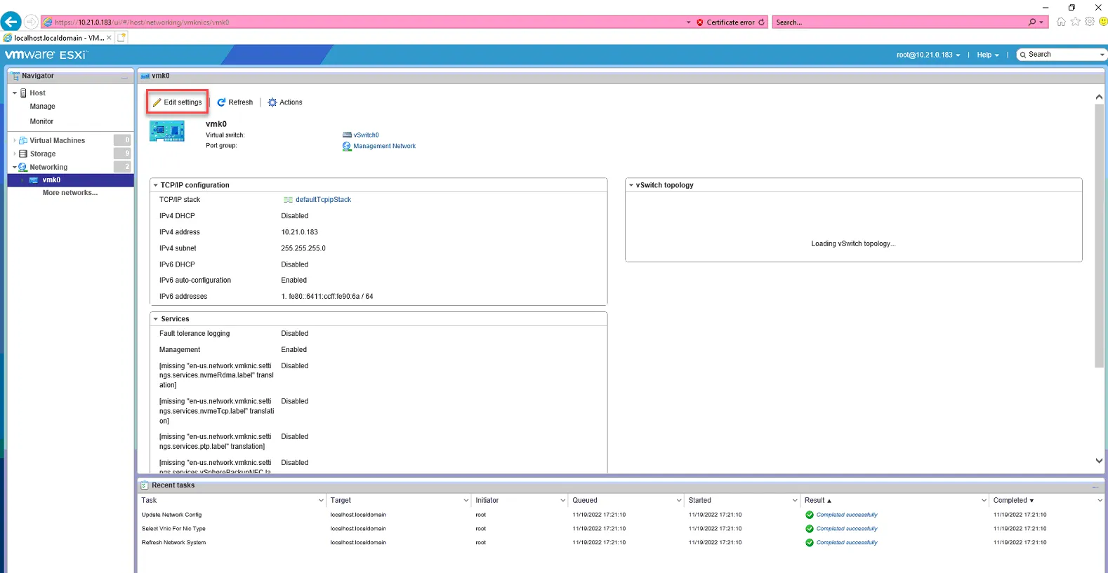
Set IP version to IPv4 Only, and uncheck Management. Click Save.
We’ve now removed vmnic0 from management on the 10.21.0.x subnet. The next time we reboot the server, it will boot from ISCSI-B. Later on, once we join the host to vcenter, we will reapply the distributed switches which will configure ISCSI-A to the vcenter standards.
Reboot the host.
Configure ESX Host Settings
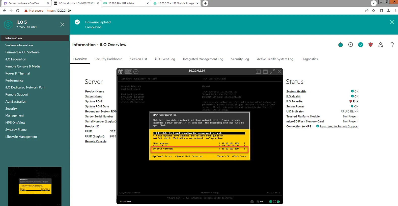
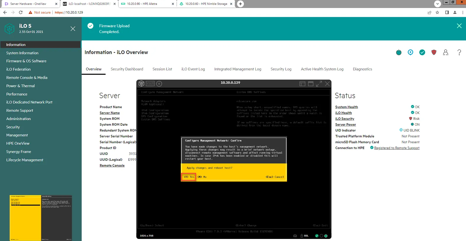
Section titled “Configure ESX Host Settings”We will not configure the hostname, DNS, etc on the host. Log into the iLO of the host. It should be on the ESXi page once it has completed booting. Verify the IP listed is the 10.10.101.x IP Address. Press F2 to configure settings.
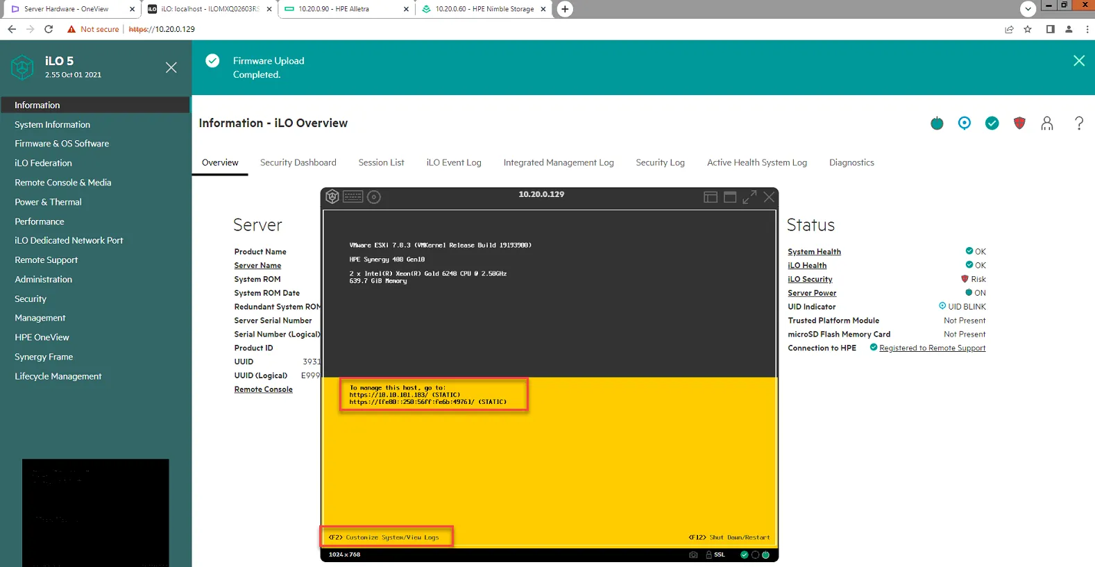
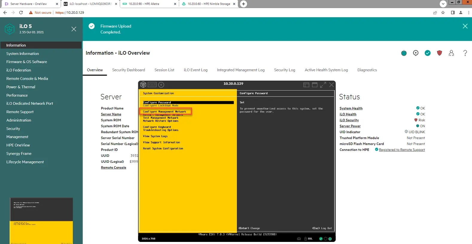
Select Configure Management Network
Select IPv4 Configuration. Then set Default Gateway to 10.10.101.100. Press Enter to save.
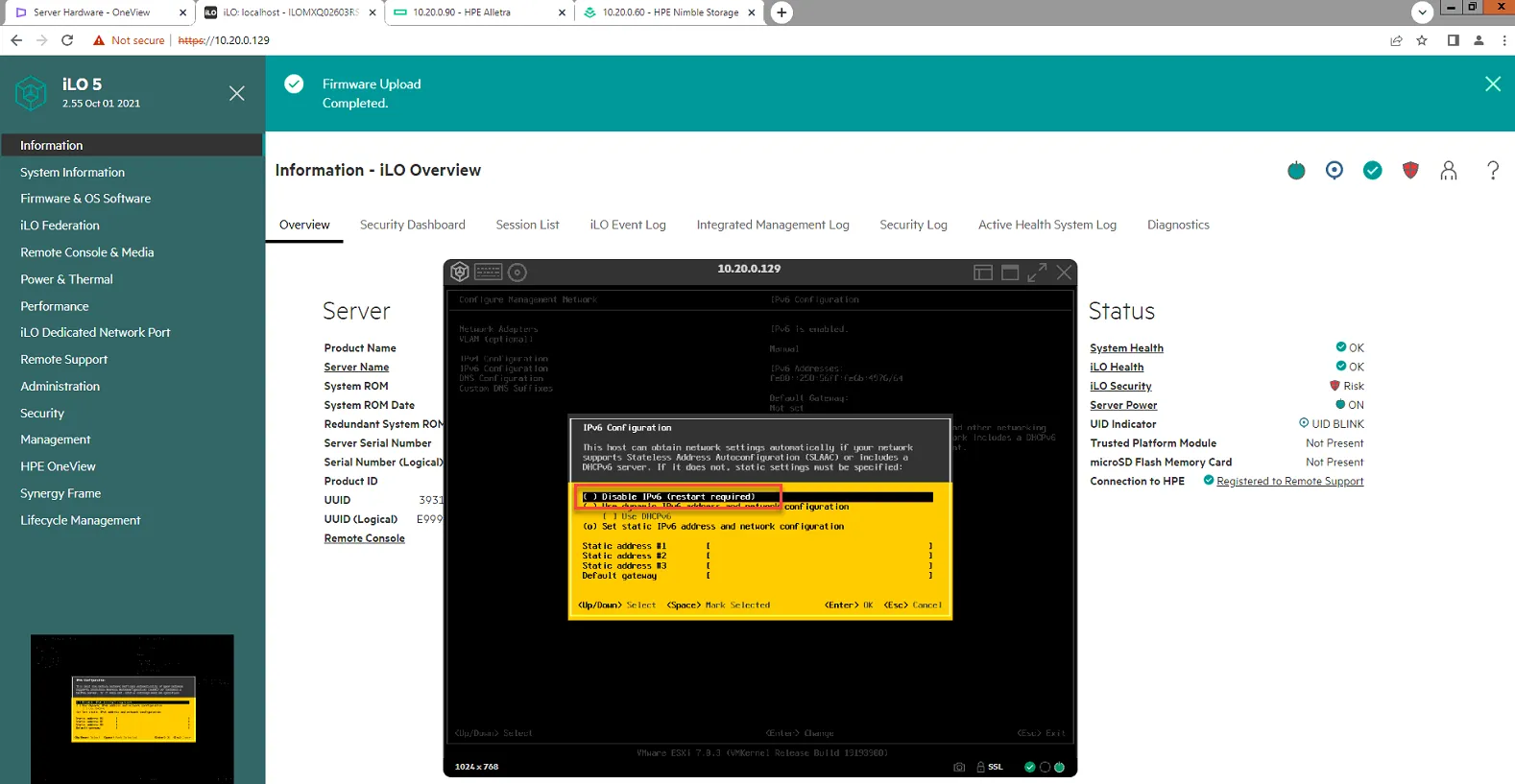
Select IPv6 Configuration, then select Disable IPv6.
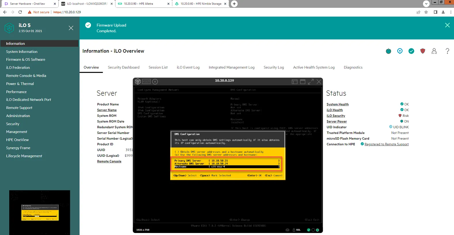
Select DNS Configuration.
Set Primary DNS Server to 10.10.50.21
Set Secondary DNS Server to 10.10.50.24
Set hostname to cit-esx-X, where X is the number of the host. In this example, we are updating host4, so hostname is cit-esx-4
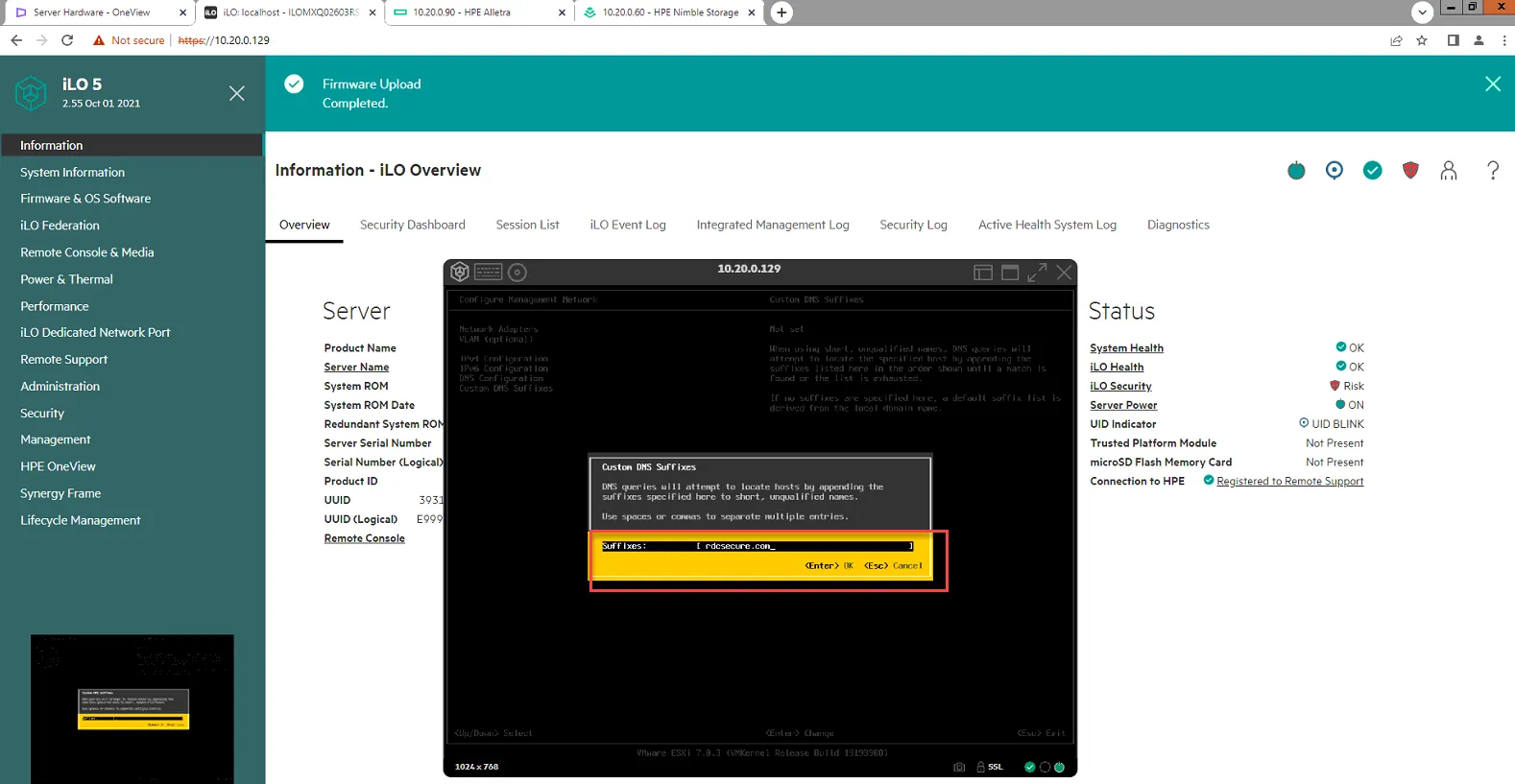
Select Custom DNS Suffixes, and set to rdcsecure.com
Press Esc to exit. Then Press Y to reboot.
Configure Additional Host Settings
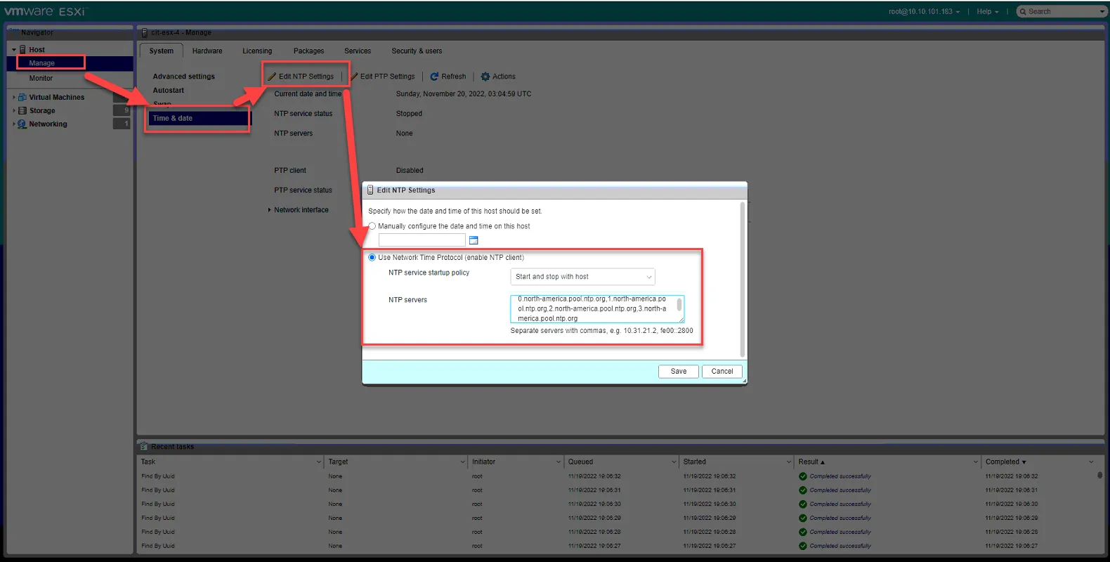
Section titled “Configure Additional Host Settings”Log into the hosts web UI via IP.
Set time protocol under Manage, Time and Date, Edit NTP Settings.
Select Use Network Time Protocol.
NTP Service Startup Policy - Start and stop with Host
NTP servers: 0.north-america.pool.ntp.org,1.north-america.pool.ntp.org,2.north-america.pool.ntp.org,3.north-america.pool.ntp.org
Click Save.
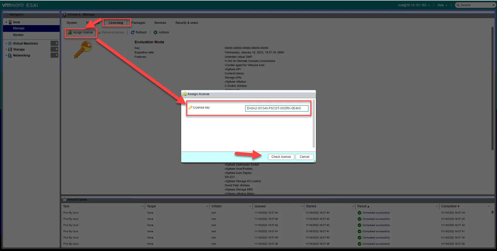
License server by clicking licensing tab, Assign License, and paste the following license key: DN0A2-0W340-P8CGT-00GRK-8E4K0
Click Check License.
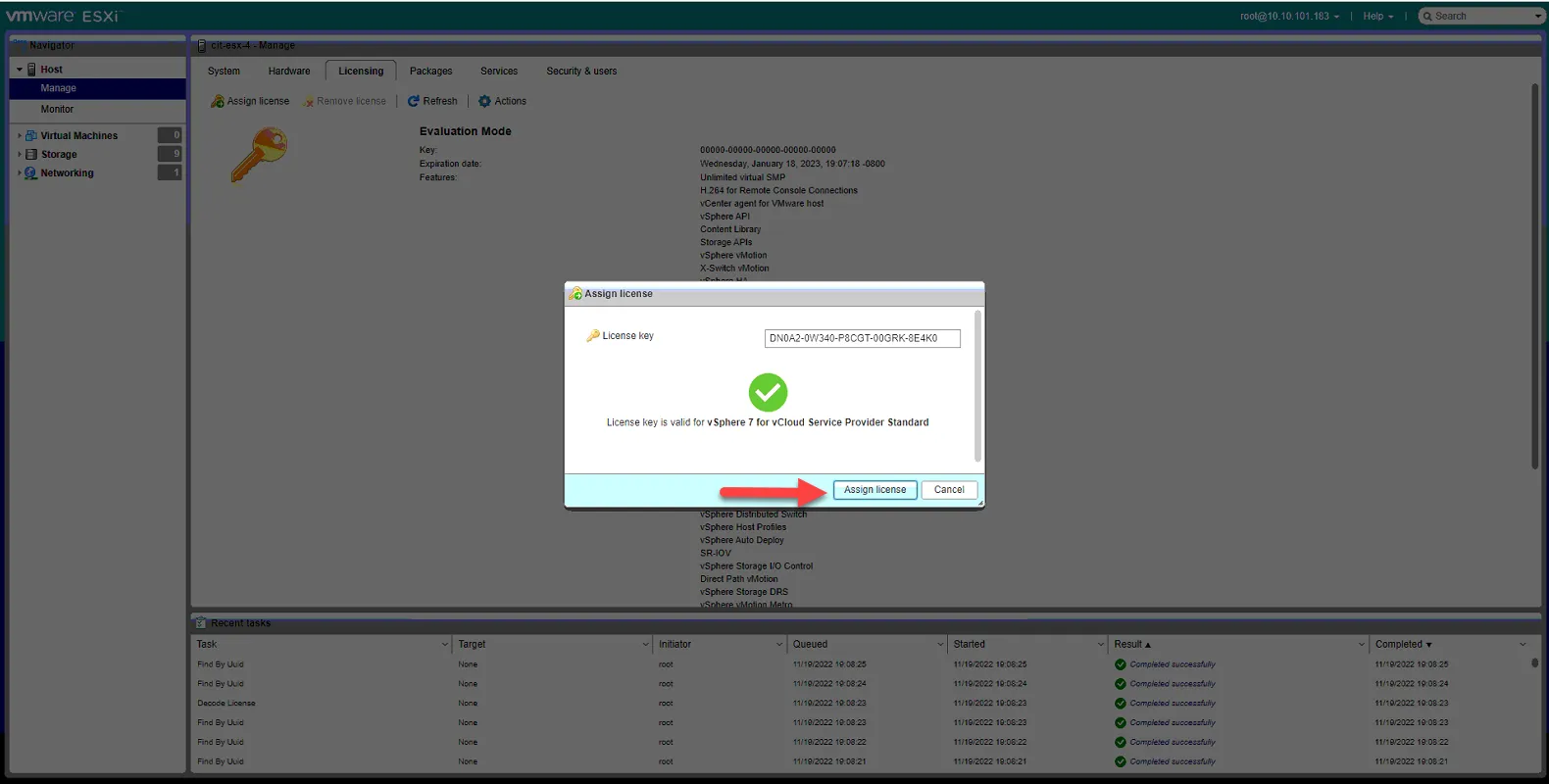
Click Assign License.
Change advanced settings to allow self signed cert (for our LDAPS server).
Go System Tab, select Advanced Settings, search for “cert”
Select “Config.HostAgent.ssl.keystore.allowselfsigned” and select Edit Option. Set value to True. Then Click Save.
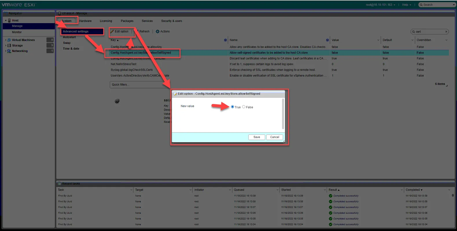
You may close out this window.
Add Updated Host to vCenter
Section titled “Add Updated Host to vCenter”Now that the host has been updated to ESX 7.0, all networking settings configured, and all other pre-requisites met, we can now add it to our vCenter.
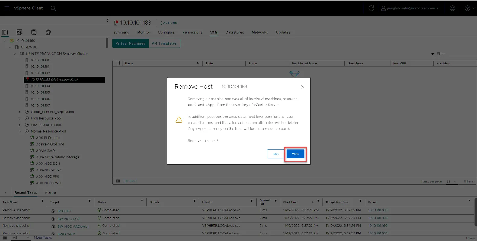
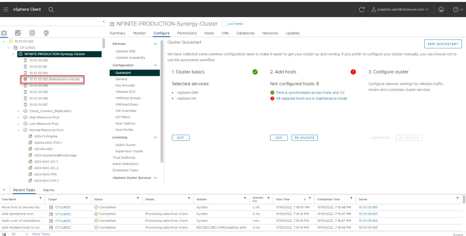
Log into vcenter (10.10.101.160). Once logged in, select the host to remove. Right click on the server, then select Remove from Inventory.
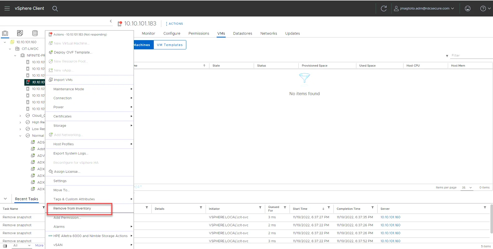
Click Yes to remove.
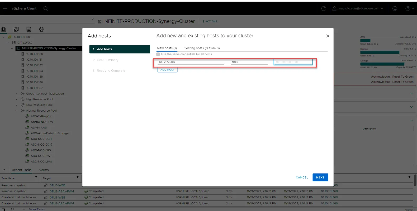
Right Click on NFINITE-PRODUCTION-Synergy-Cluster, and select Add Hosts…
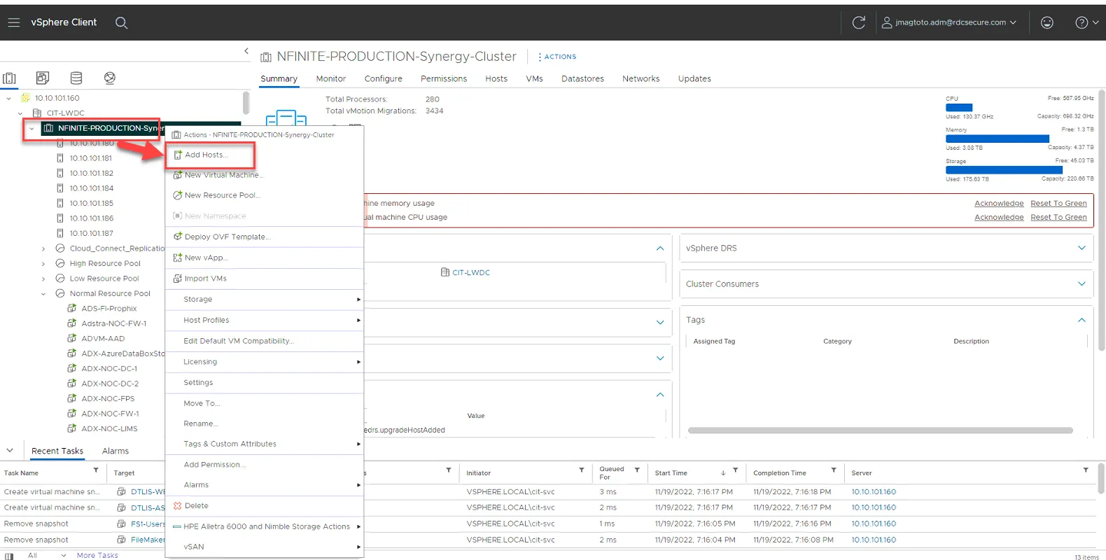
Add the IP of the host, and credentials. Click Next.
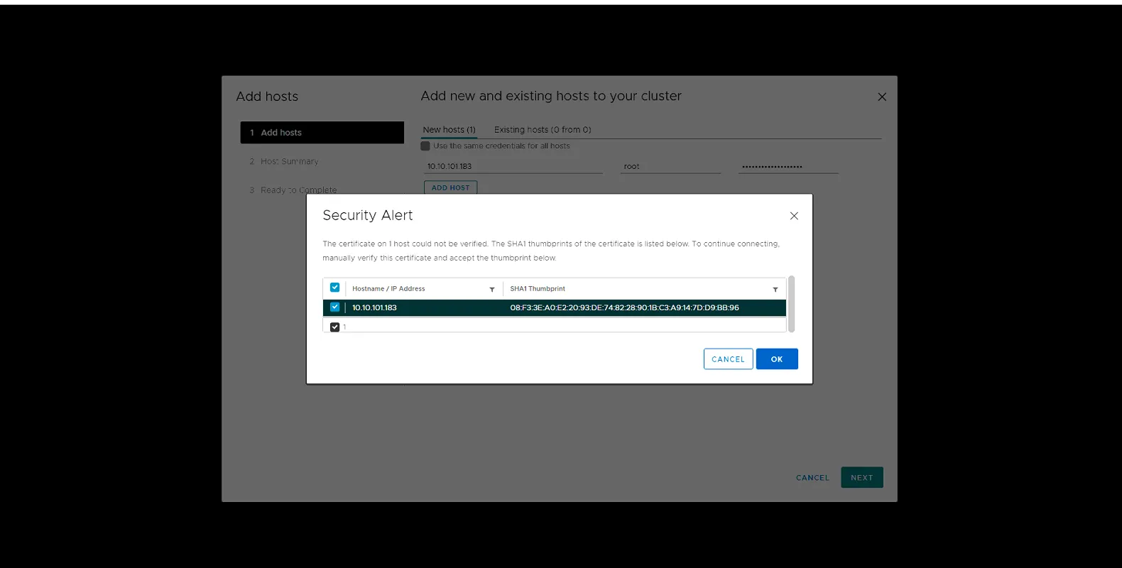
Click Ok to bypass Security Alert
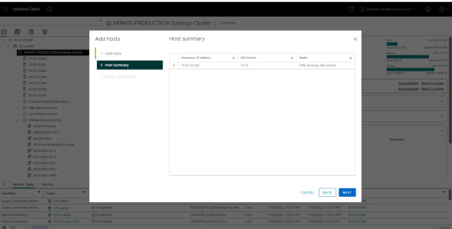
Click Next
Click Finish
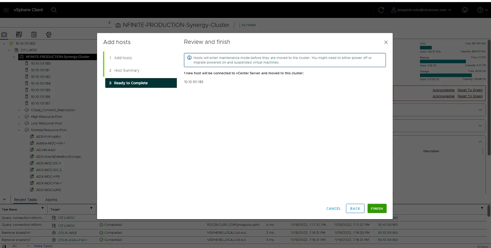
Host will now be added to vcenter and should be listed within the cluster.
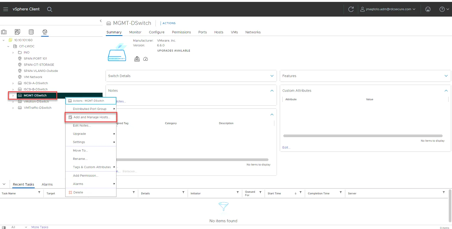
Configuring Distributed Switches for the Host
Section titled “Configuring Distributed Switches for the Host”Now that the host is in vcenter, we can now add the host to the distributed switches in vcenter. Click on Networks.
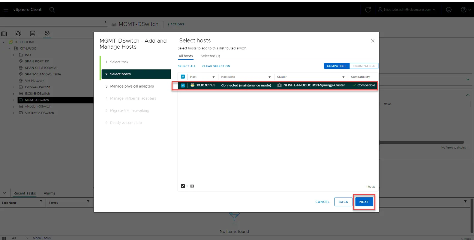
Right Click on MGMT-DSwitch, and select Add and Manage Host…
Select Add Hosts, then click Next
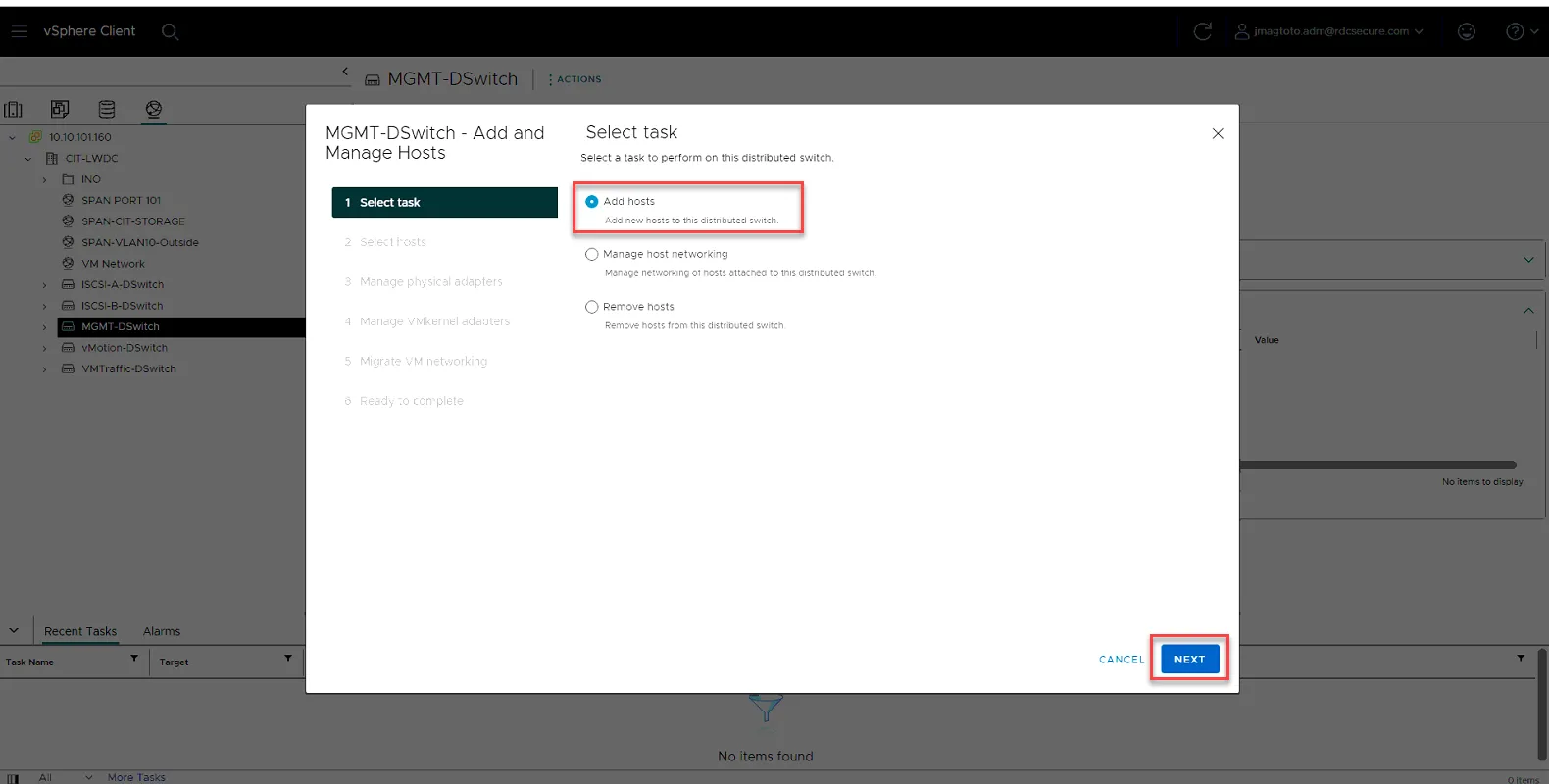
Select the host, then click Next.
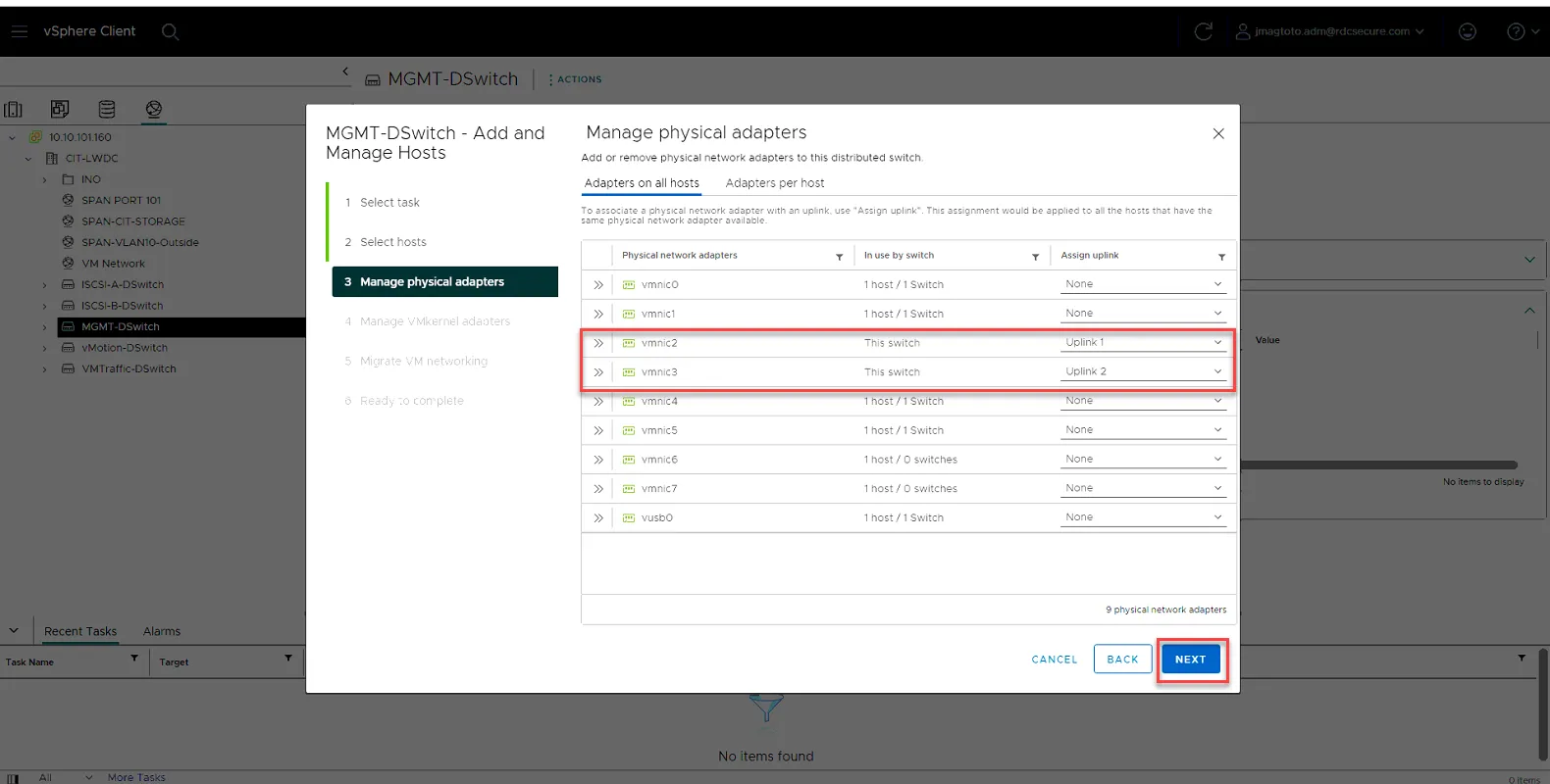
Set vmnic2 and vmnic3 to Uplink1 and Uplink2. Click Next.
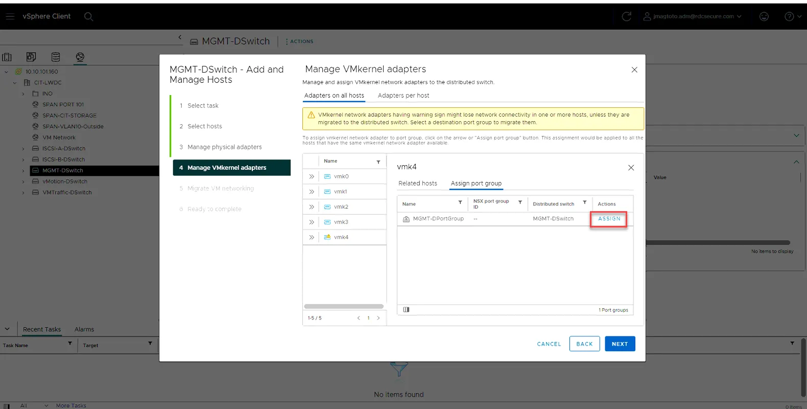
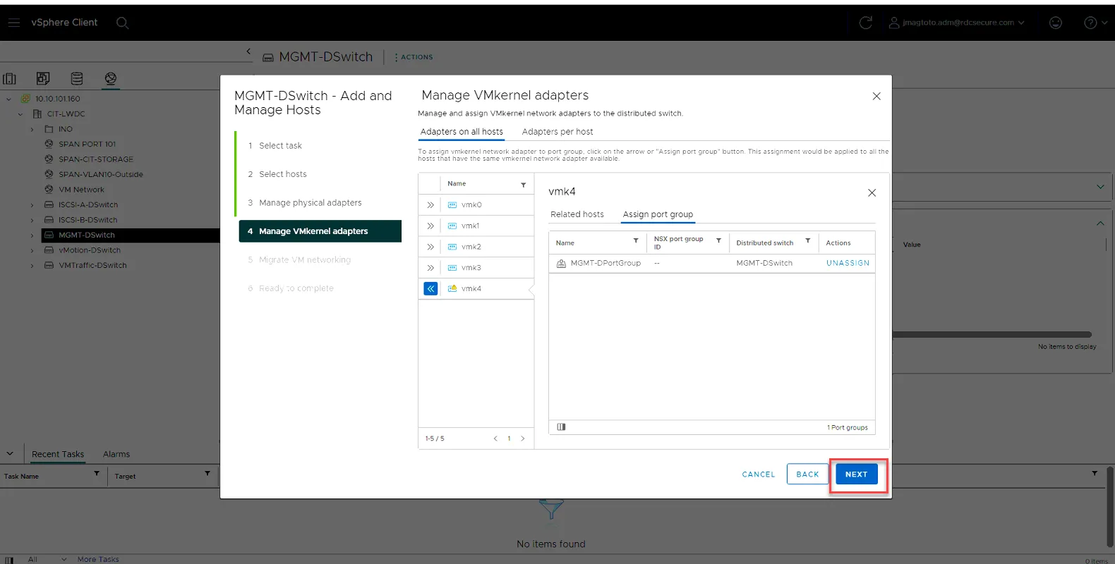
Click vmk4 and click Assign Port Group
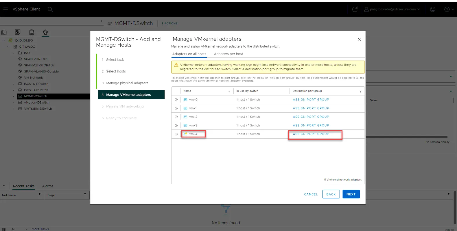
Then click Assign.
Then Click Next
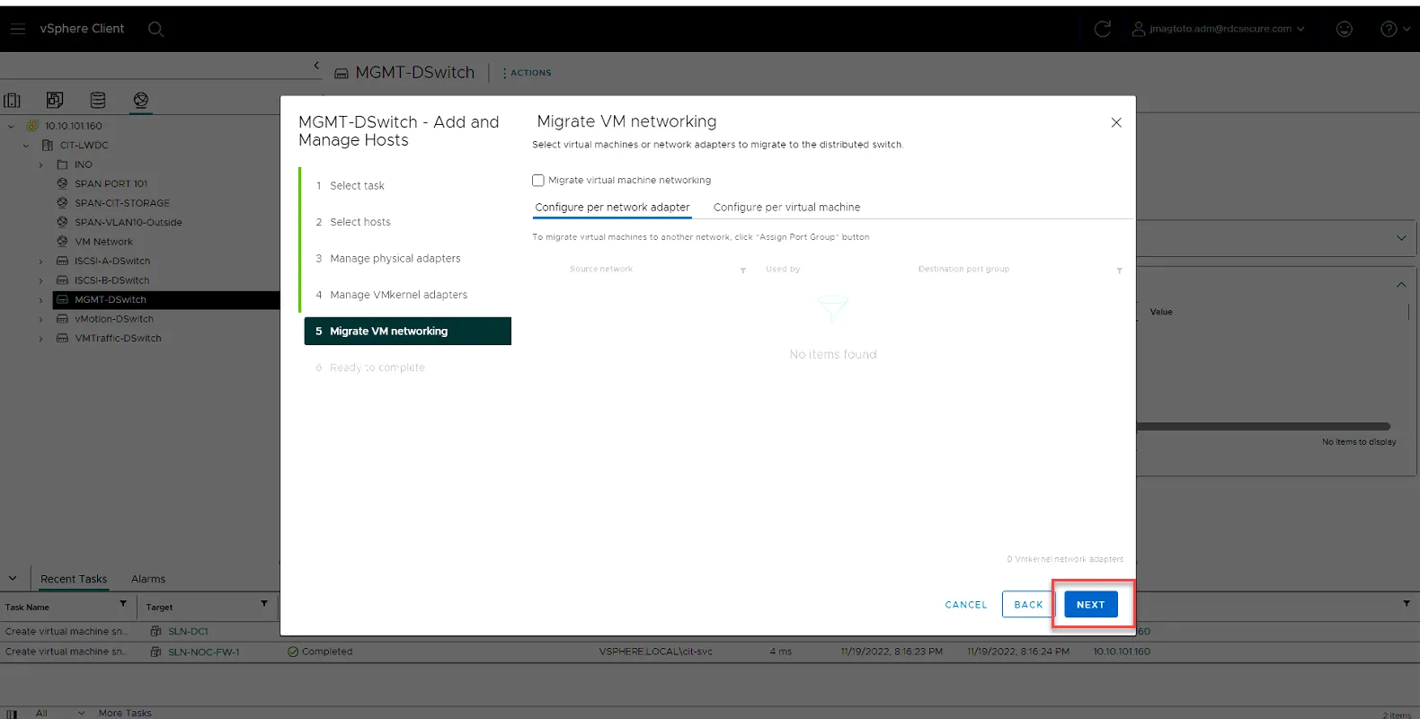
Click Next.
Click Finish
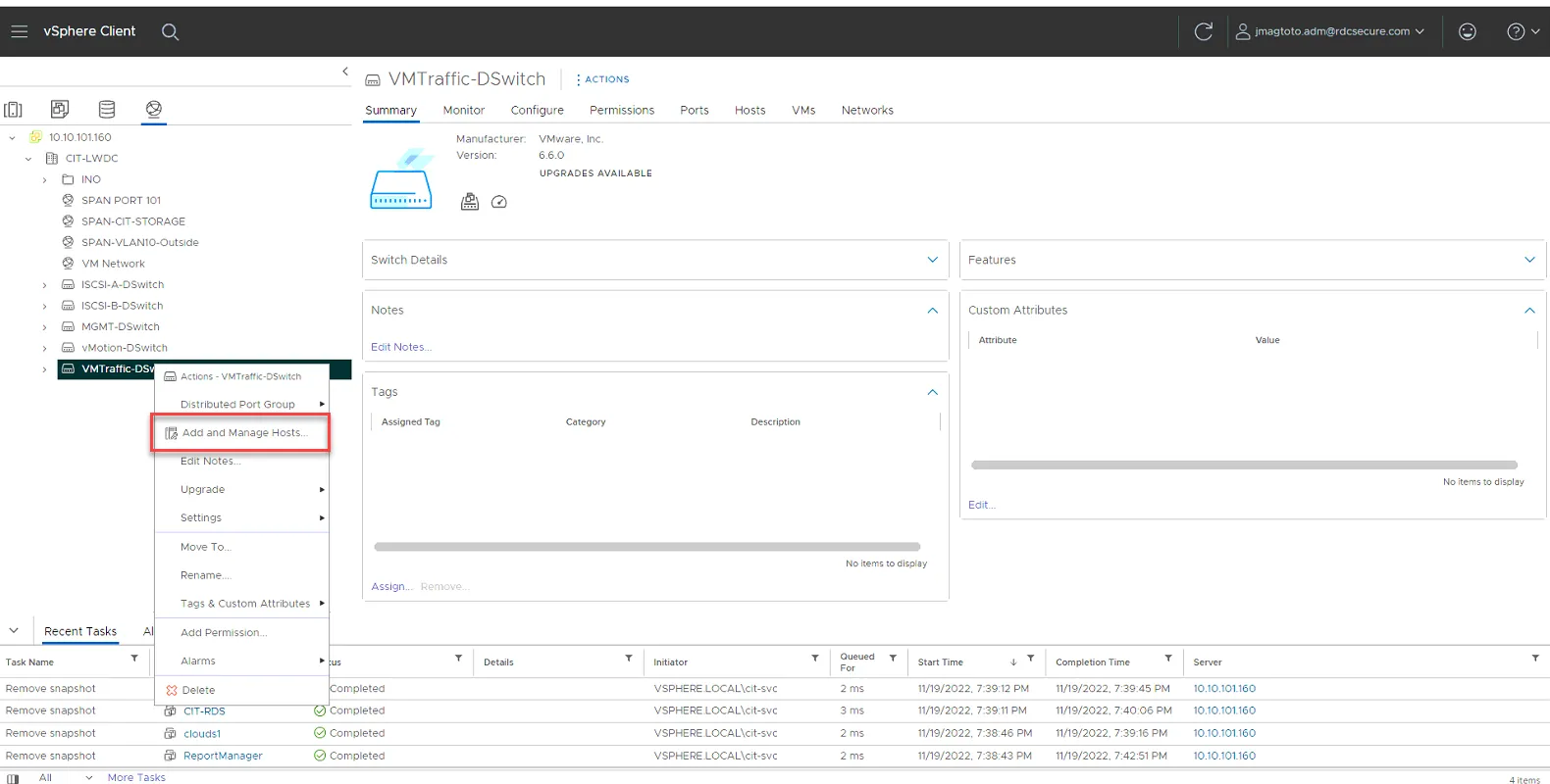
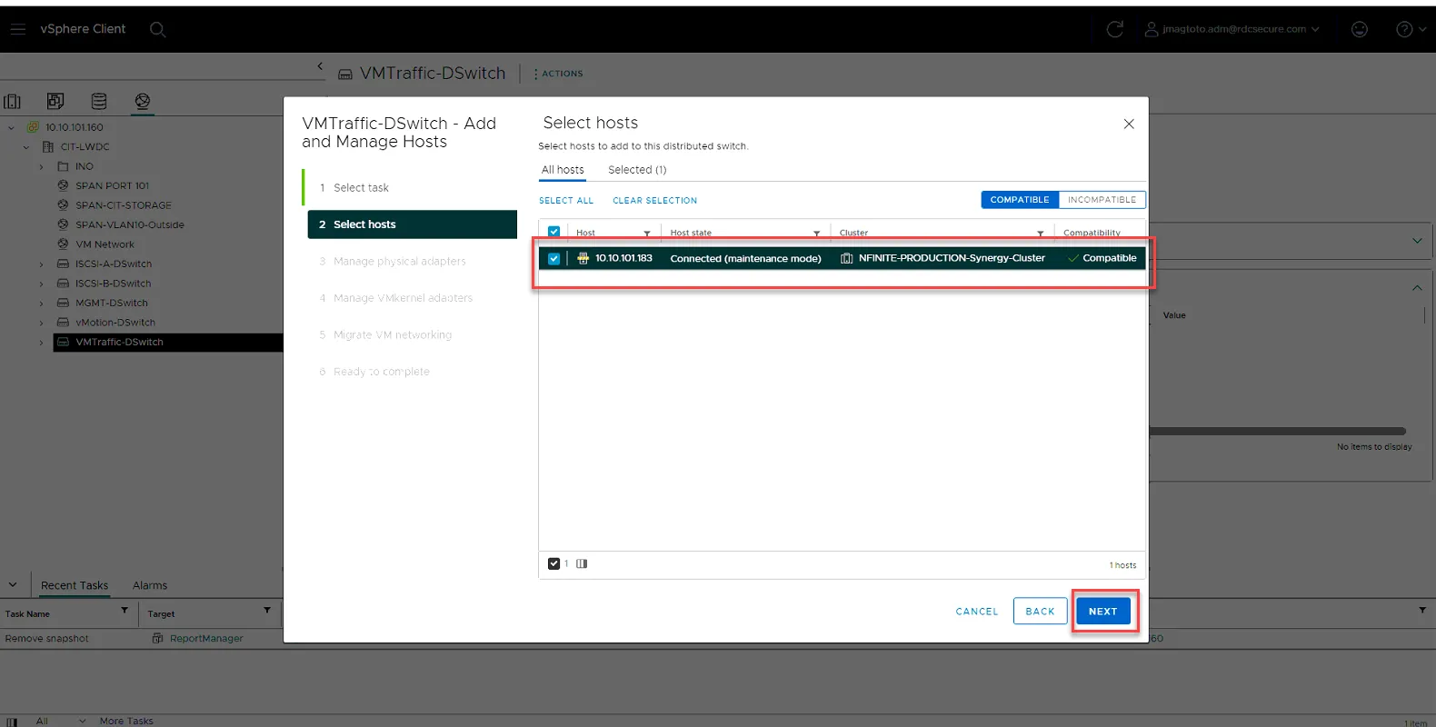
Right click on VMTraffic-DSwitch, and select Add and Manage Host…
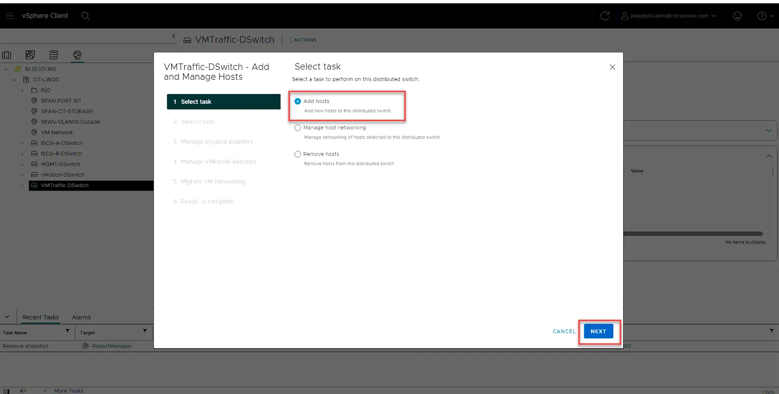
Select Add host and click Next.
Select the host and click Next.
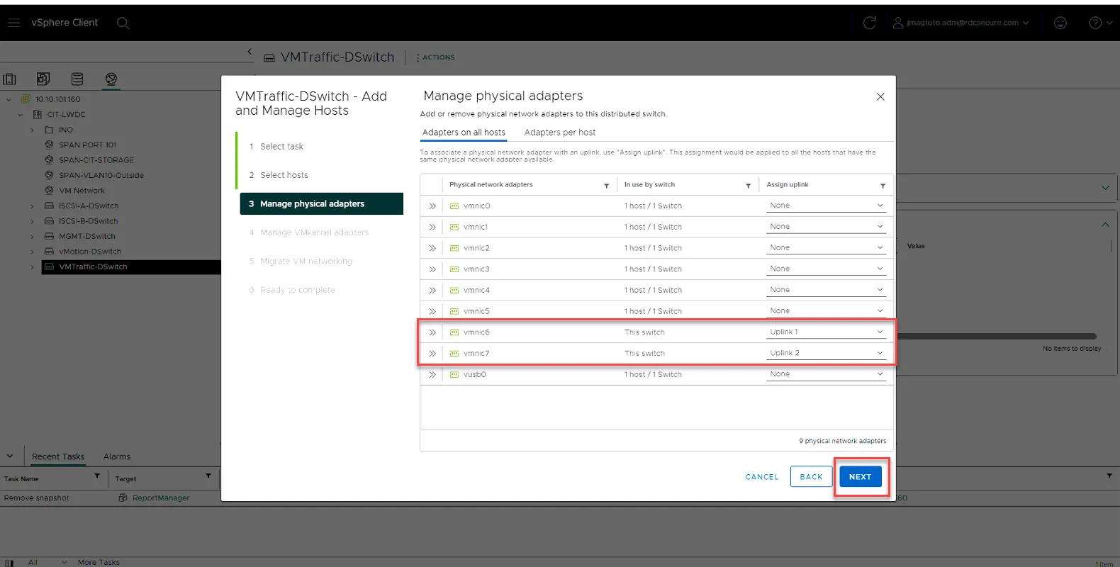
Select vmnic6 and set to Uplink 1
Select vmnic7 and set to Uplink 2.
Click Next.
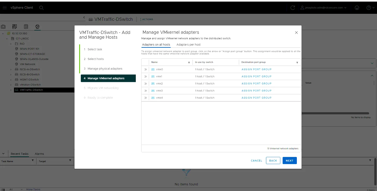
Leave everything as is and click Next.
The host has now been added to MGMT-DSwitch. Move on to the next Dswitches using the following Settings:
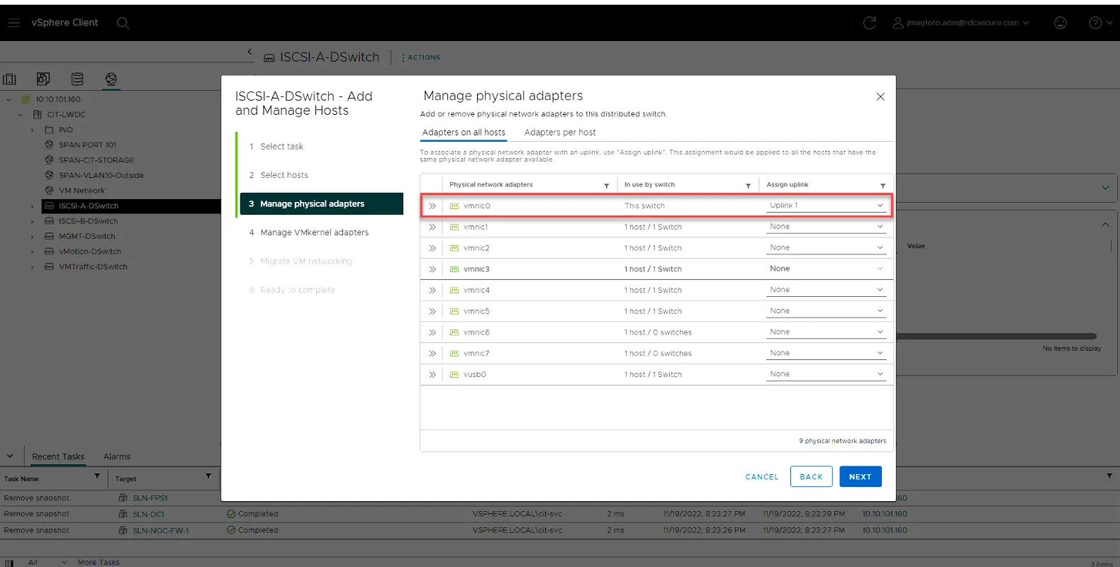
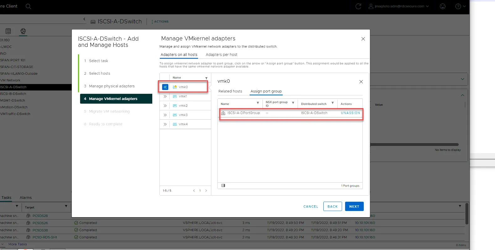
ISCSI-A-DSwitch
vmnic0 - Uplink 1
vmk0 - Assign Port Group
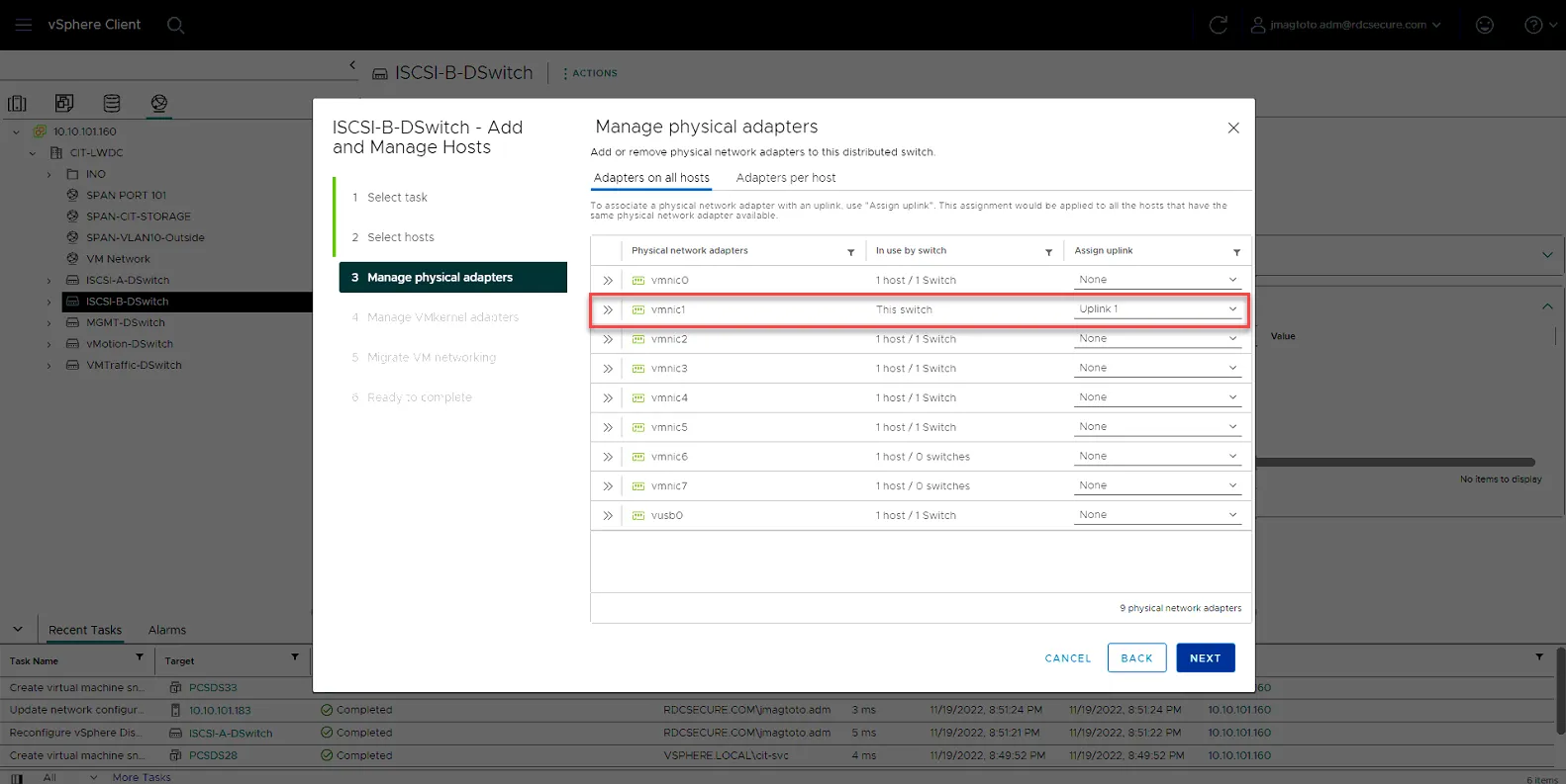
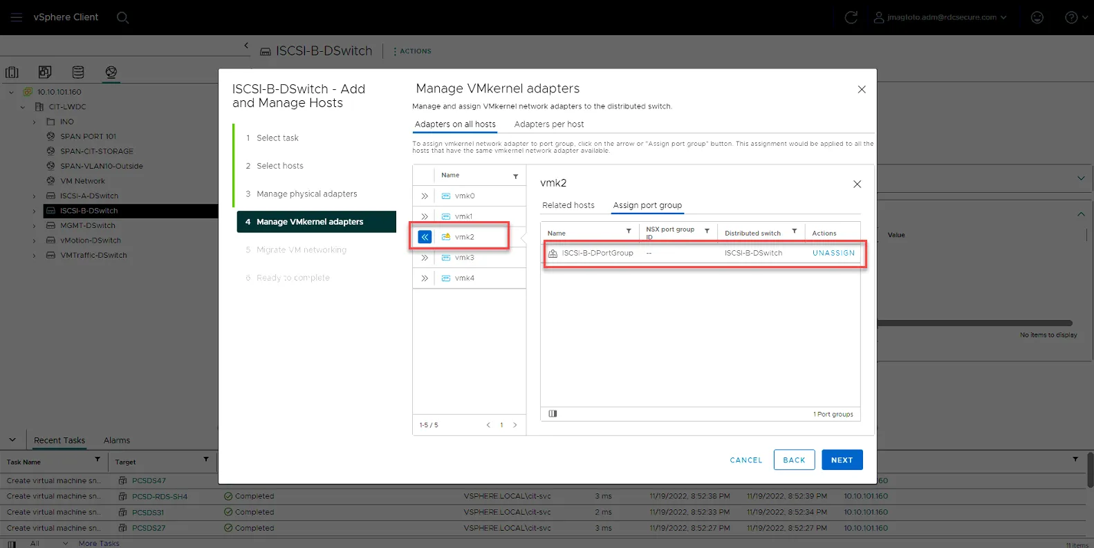
ISCSI-B-DSwitch
vmnic1 - Uplink 1
vmk2 - Assign Port Group
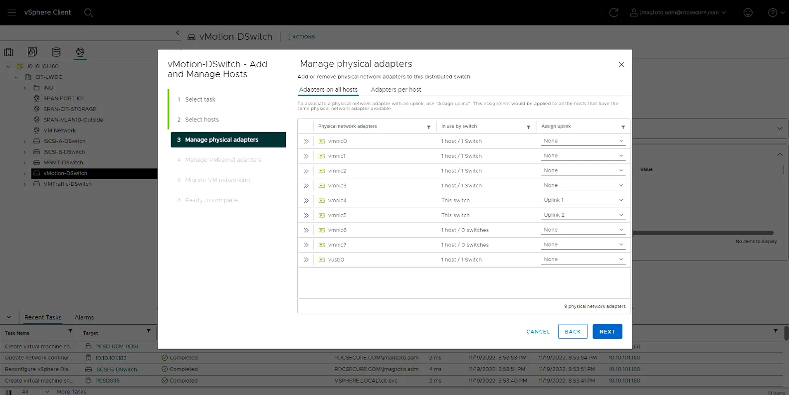
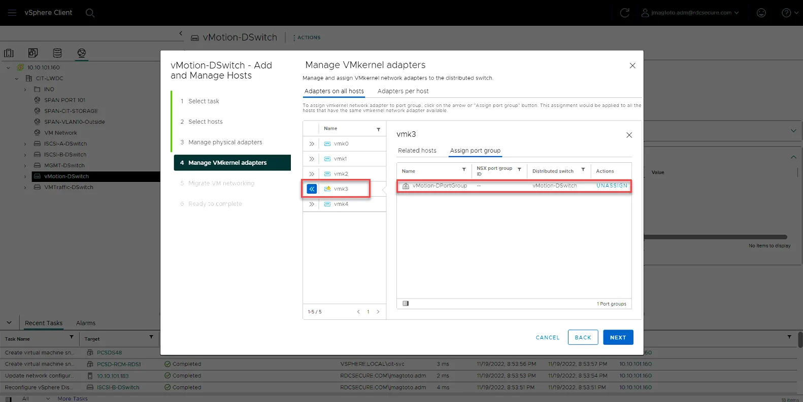
vMotion-DSwitch
vmnic4 - Uplink1
vmnic5 - Uplink2
vmk3 - Assign Port Group
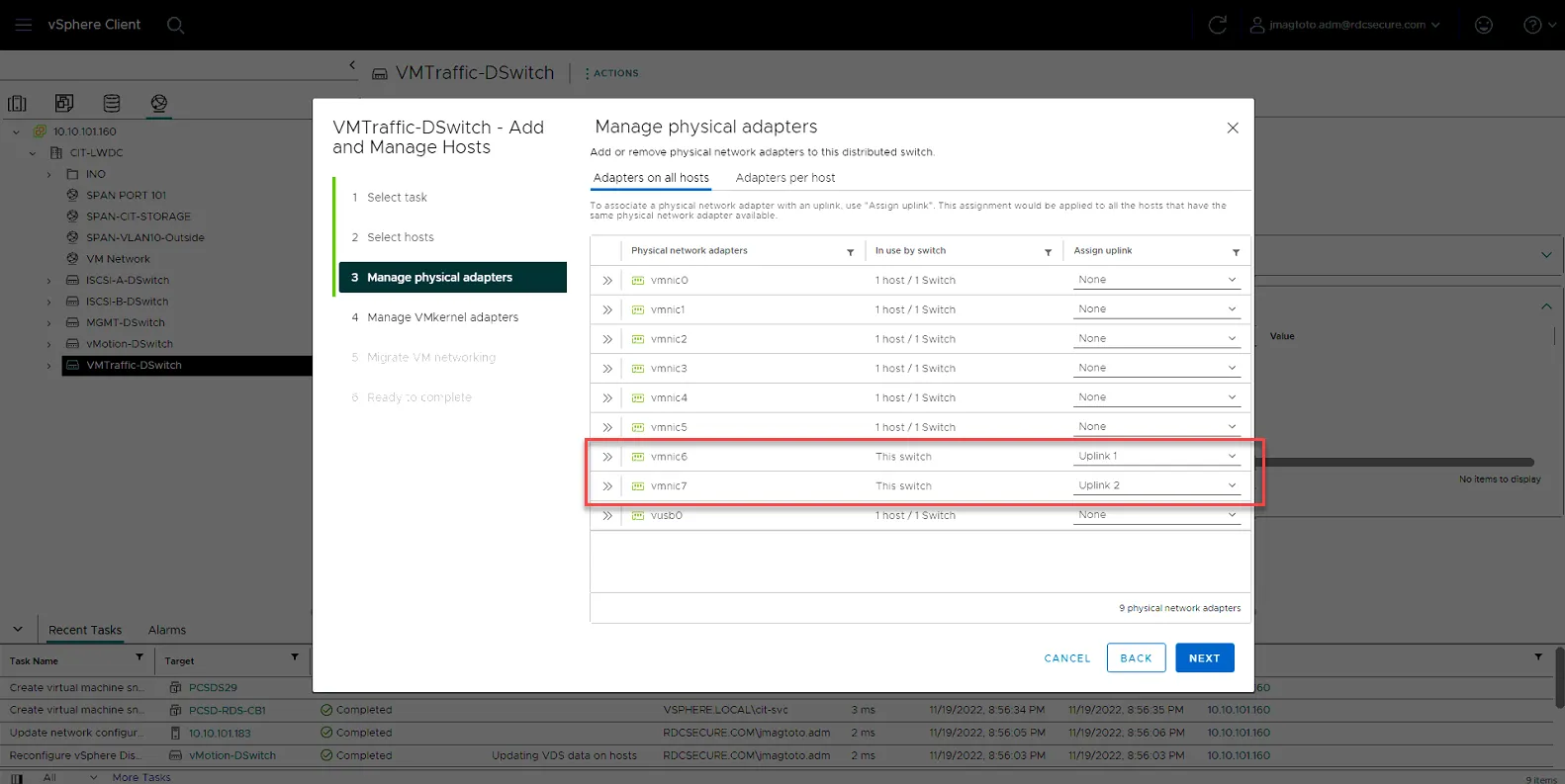
VMTraffic-DSwitch
vmnnic6 - Uplink1
vmnic7 - Uplink2
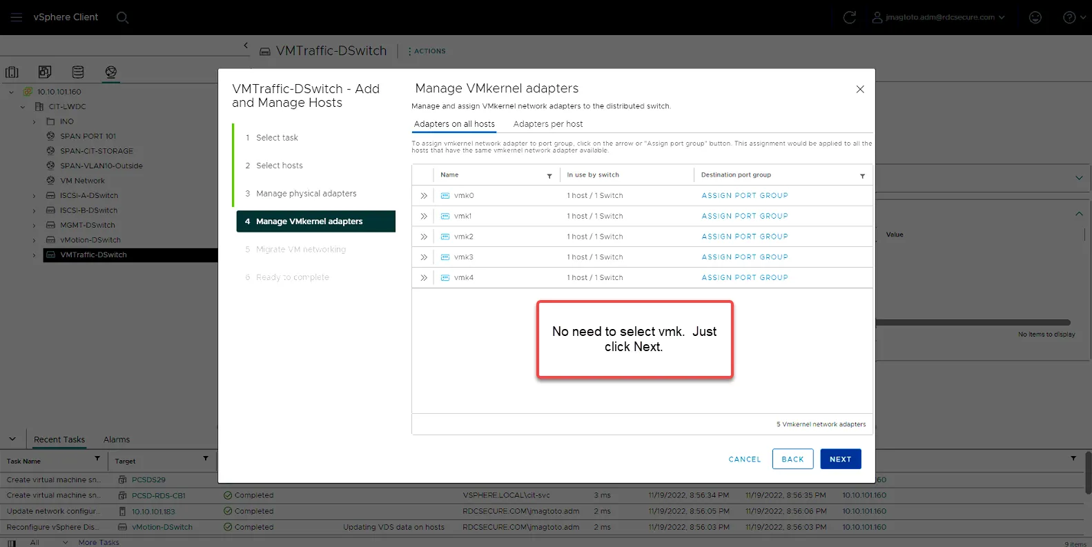
Do not set VMKernal, just click Next.
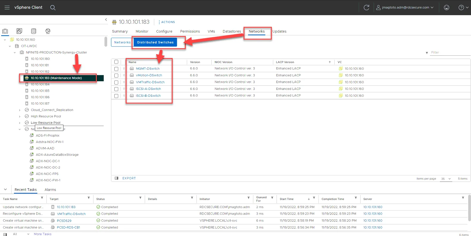
Once you’ve added the host to all the Distributed Switches, you can verify all the switches are added by click on the host, then going to Networks. All 5 of the VDS’s should be listed there.
Configure iSCSI Software Adapter
Section titled “Configure iSCSI Software Adapter”Now that the virtual Distributed Switches are configured, we can now finalize the iSCSI Software Adapter Settings so the host can discover the LUNS on the Alletra and Nimble-2.
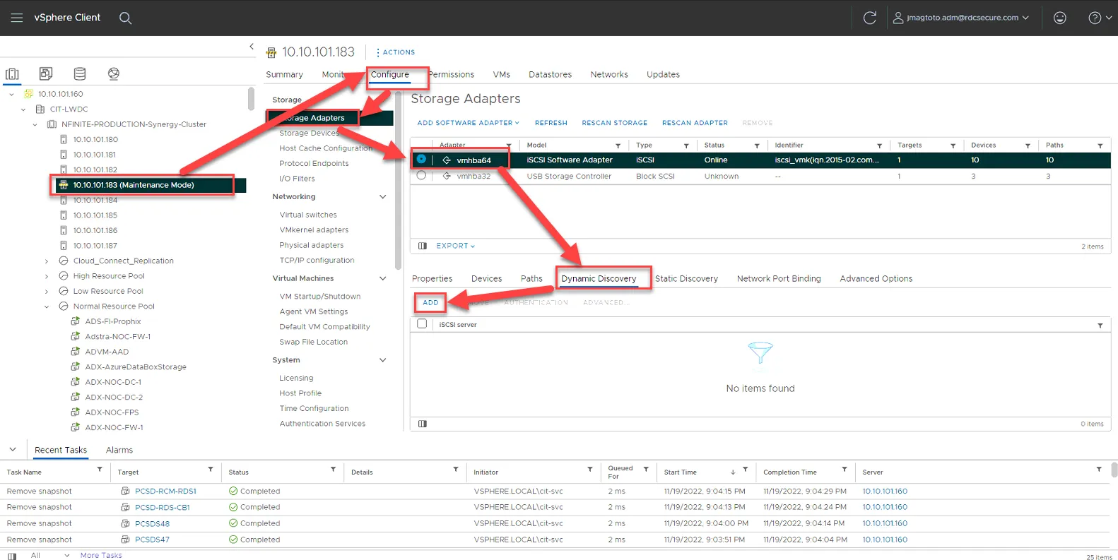
Select the Host, then Click Configure, then click Storage Adapters, then click vmhba64, then click Dynamic Discovery, then click Add.
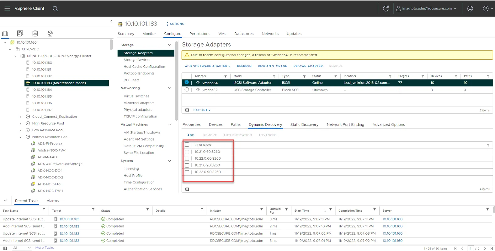
Add the following IPs one at a time:
10.21.0.60
10.22.0.60
10.21.0.90
10.22.0.90
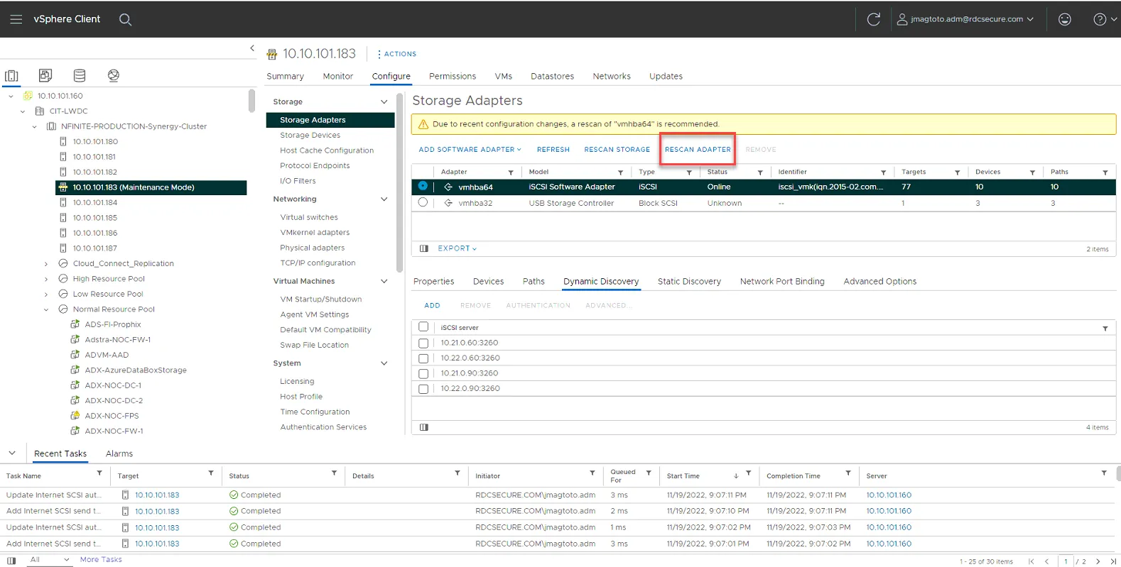
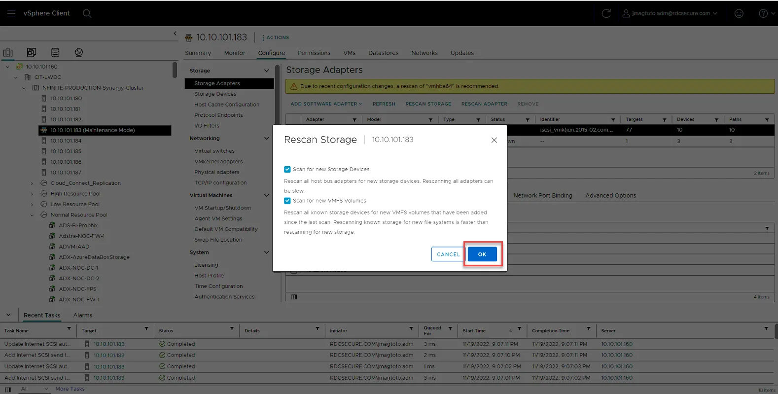
Select Rescan Adapter
Once rescan adapter has completed, Select Rescan Storage.
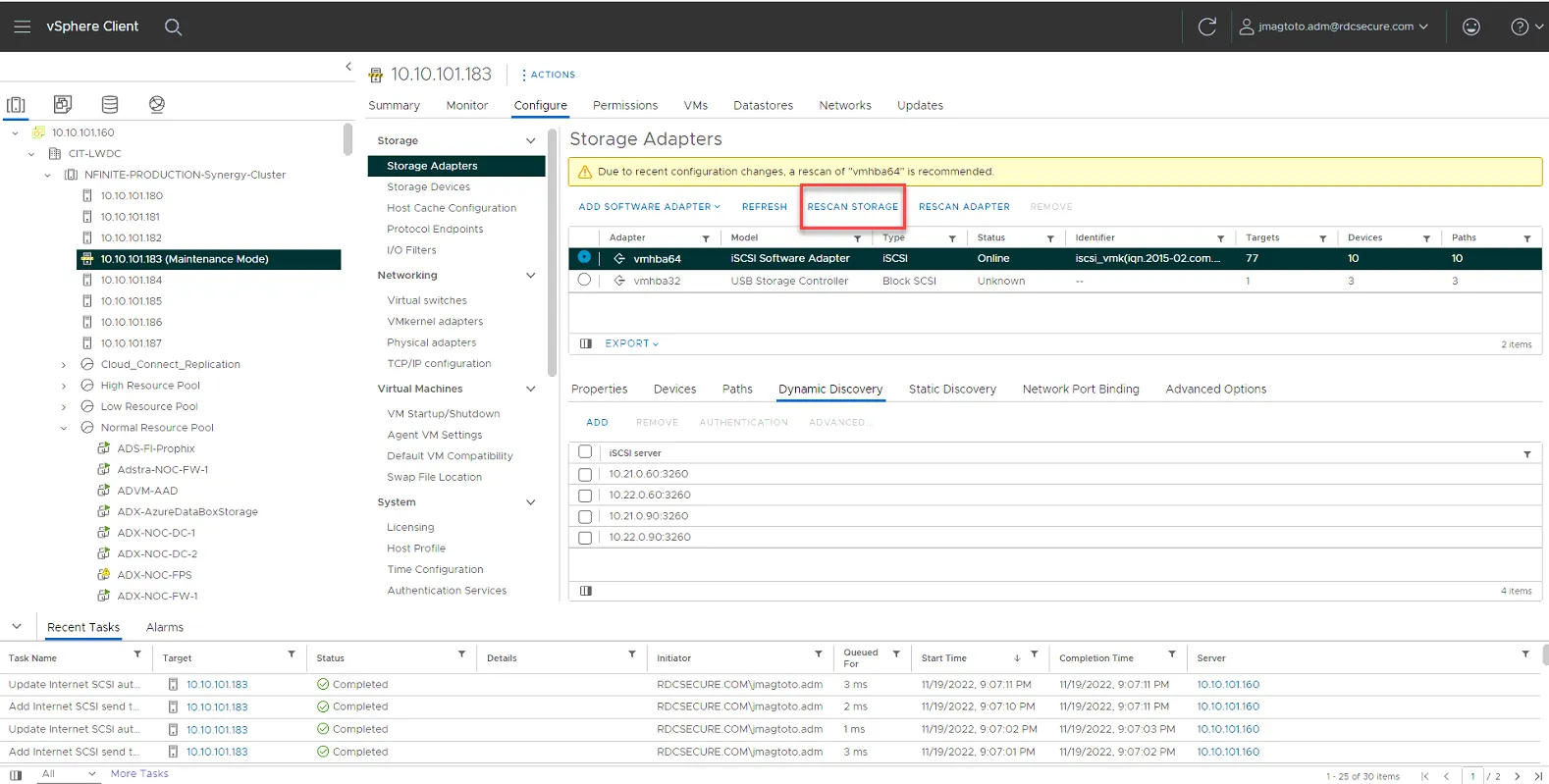
Click Ok to rescan.
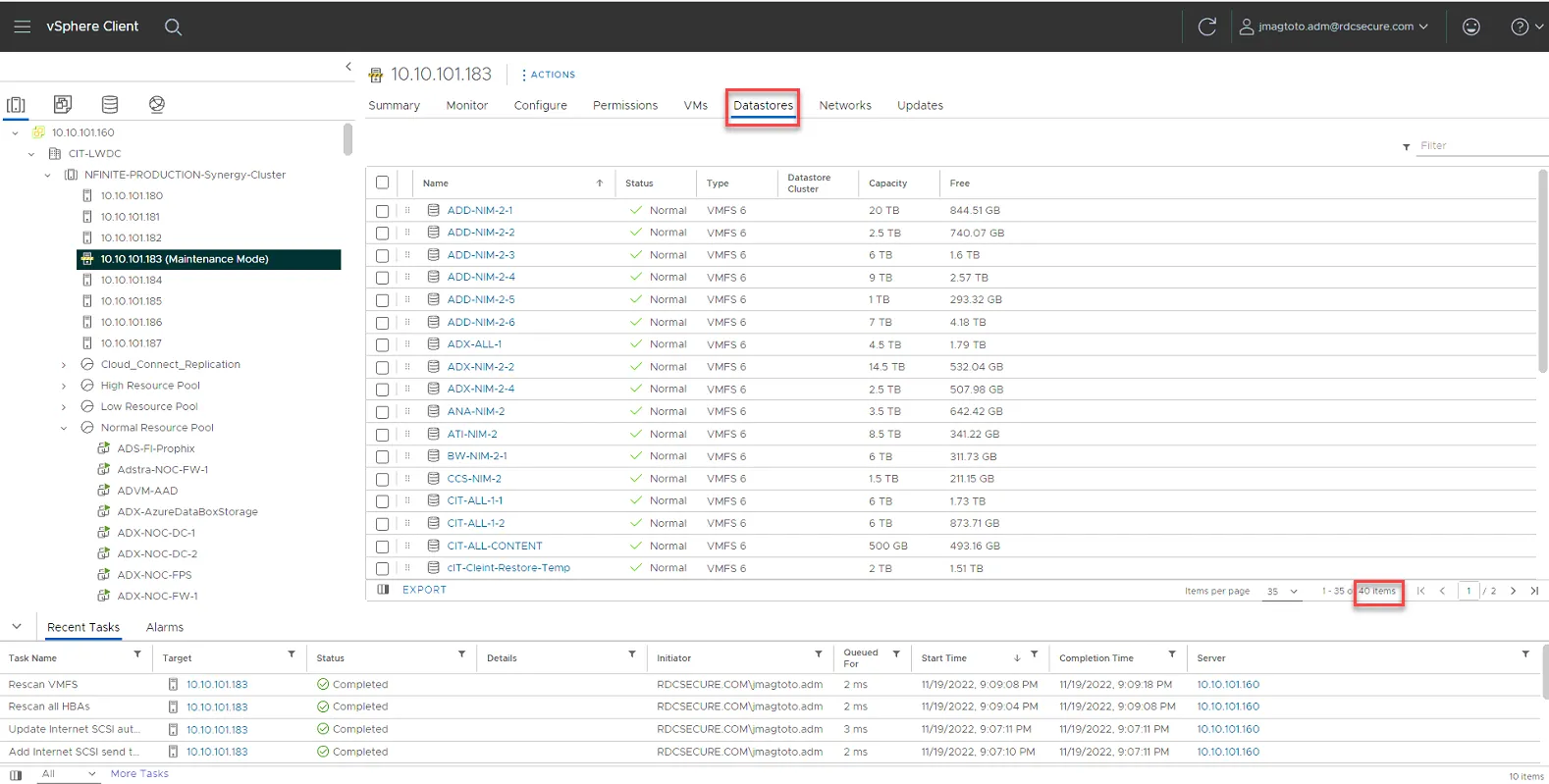
Once you are done, click on Datastores and verify you can see all the datastores. As of this writing there are 40 total datastores. Compare it against another host to ensure the number of datastores match.
Detach USB Storage Adapters
Section titled “Detach USB Storage Adapters”To ensure there are no issues with the USB drives, we’ll want to detach them.
Go to Configure, Storage Devices. Then sort by name so Local USB Direct-Access is listed at the top.
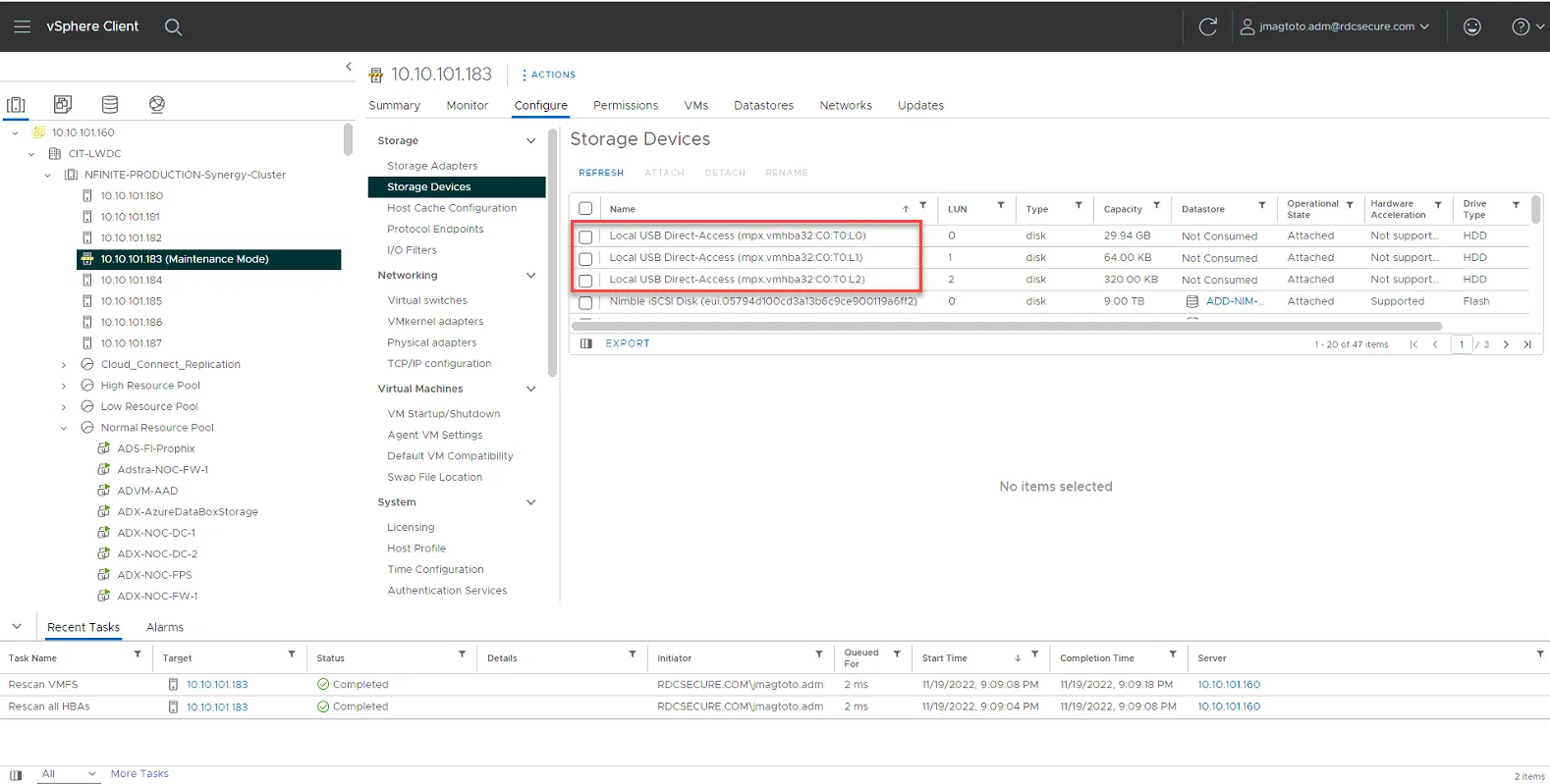
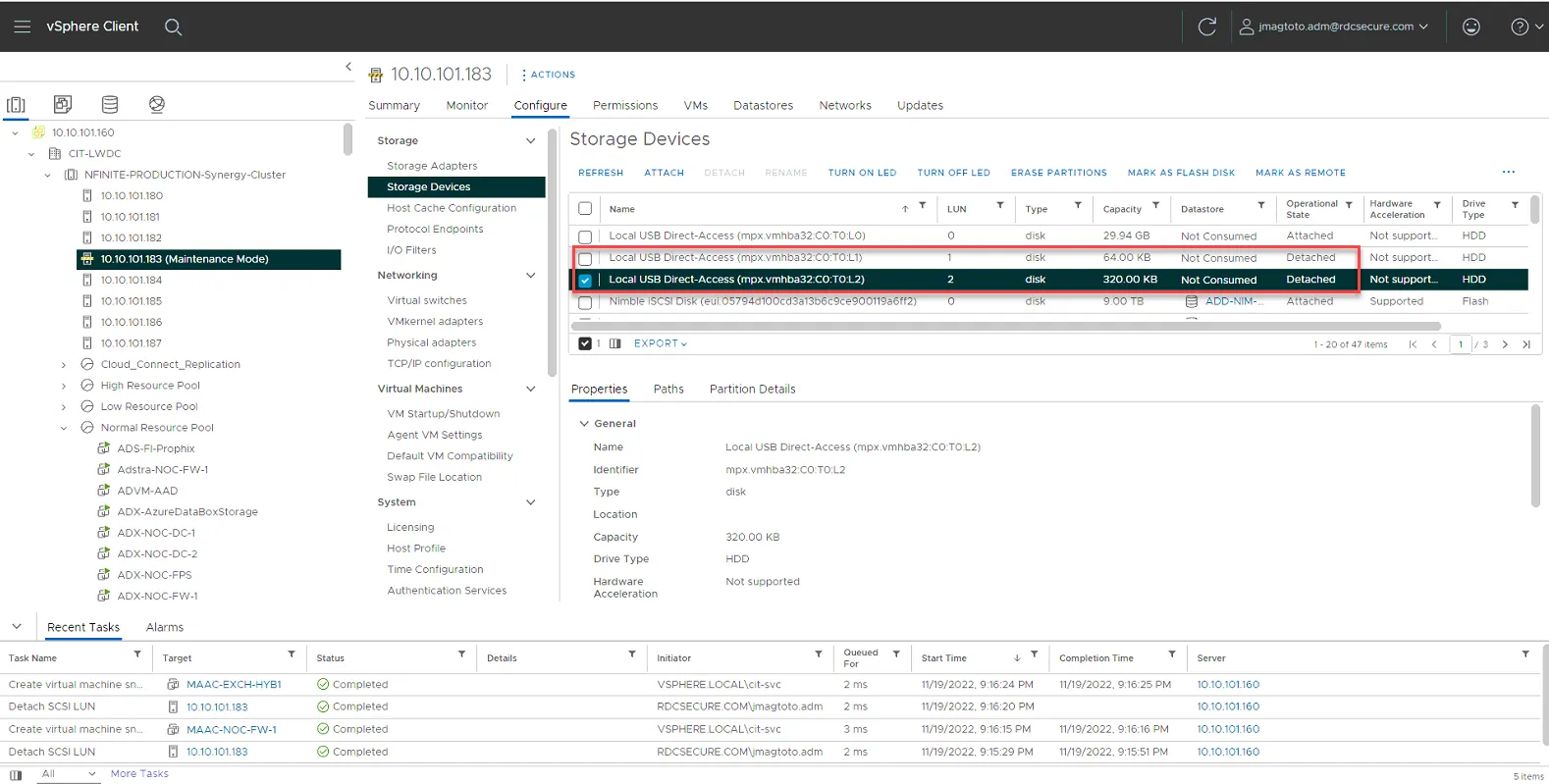
For each Local USB storage, select it then select detach. The first USB with LUN0 may error out. If so, skip it and detach the next two.
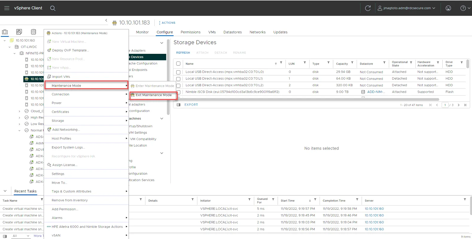
Remove server from Maintenance mode
It will now install the vSphere HA agent.
Install NCM on Host from SSH
Section titled “Install NCM on Host from SSH”Enable SSH
SSH into the host, then run the following command
esxcli software component apply -d https://update.nimblestorage.com/esx7.0/ncm
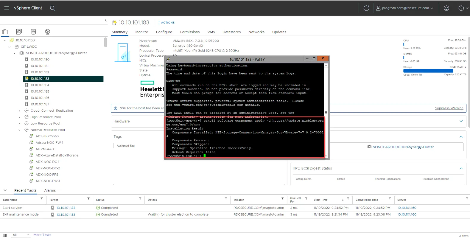
Turn off SSH.
WE ARE DONE!!!
You can now vmotion a few non-critical VMs to the host and monitor performance for the next day and move on to the next host.
END.